Basic Refrigeration: Major Components in the System
This second part of the series describes what techs need to know about components

Before technicians can think about installing a refrigeration system — or troubleshooting one — they need to understand the major components of that system. Part 1 of this series covered the basics of heat transfer, while this article will look at the different components that make up a standard refrigeration system.
Compressor
As the heart of a refrigeration system, the compressor is a vapor pump that creates the system’s required pressure differences between the low and high sides of the system. In addition, it raises the temperature of the refrigerant to a usable level. The temperature of the refrigerant must be higher than the ambient air, or else there won’t be heat transfer. Heat always flows from a hotter source to a cooler source, so to be rejected, the refrigerant must be hotter than the outdoors. Only then will the heat transfer take place.
The compressor must also be able to pump a sufficient volume of refrigerant, and it must be able to accommodate the refrigerants used.
Metering Device
The metering device controls refrigerant flow into the unit cooler, also called the evaporator, and regulates the desired pressure of the boiling point of the refrigerant. If the pressure of the refrigerant can be lowered, it can boil at a lower temperature.
When it’s at the boiling point, it’s ready to absorb a fresh load of heat. The heat comes from the air that is being pushed across it from a fan that is running across the evaporator. If that air is warmer than the boiling refrigerant, and it comes in contact with the cooler coils, then there will be heat transfer into the refrigerant.
Like the compressor, the metering device must be sized appropriately and must be compatible with the refrigerants used. This device’s main job is to maintain the proper superheat to protect the compressor from the liquid that can travel through the suction line if the temperature is too cool.
There are two main types of metering devices: the thermostatic expansion valve (TXV) and the electronic expansion valve (EEV). Although mechanical TXVs are reliable, EEVs are much more accurate and responsive to changes in pressure and temperature. Figure 1 compares their efficiency, starting at 30°F. With the TXV, it takes about two hours to get to 10°F superheat, and with the EEV at steady-state operation, it takes dramatically less time.
Looking for quick answers on air conditioning, heating and refrigeration topics? Try Ask ACHR NEWS, our new smart AI search tool. Ask ACHR NEWS

Figure 1
TXV VS. EEV: Comparing the efficiencies of the TXV (blue line) and the EEV (red line). (Courtesy of Heatcraft)
If using a TXV, the sensing bulb placement, which is detailed in Figure 2, is important. A solid connection is needed, because heat must be transferred into the sensing bulb from the pipe. It should be well insulated, because its job is to sense the temperature of the pipe, rather than the air around it. In Figure 3, oil in the line may insulate the true temperature of the vapor, so the sensing bulb must be above the perceived oil line to get an accurate reading. Although these numbers can be used as a guide, always check the guidelines from the valve manufacturer to determine proper placement.
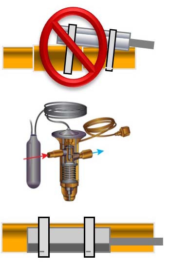
Figure 2
BULB PLACEMENT: If using a TXV, the sensing bulb placement is important. (Courtesy of Heatcraft)
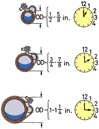
Figure 3
PIPE TEMPERATURE: The TXV’s job is to sense the temperature of the pipe, rather than the air around it. (Courtesy of Heatcraft)
The EEV has a separate sensing device -- a temperature-sensitive resistor called an NTC, which changes resistance value based on temperature. NTC stands for negative temperature coefficient, which means when temperature goes up, resistance goes down. The thermistor usually is set at 10,000 ohms at a certain temperature, generally at 77°F (or 25°C). Because this type of sensor is used for all measuring needs, most manufacturers use three thermistors; however, for defrosting, some use a bimetal device with different rates of expansion. This device can make or break a circuit, depending on its temperature.
Other Components
Most manufacturers use a three-wire, capacitive-type pressure transducer, which will use a flexible diaphragm to vary voltage output. Based on that output, it will translate the voltage value into a pressure value. The control will discern those differences in pressure based on the transducer output.
The crankcase pressure regulator (CPR) valve, located at the outlets of the evaporator, helps prevent compressor overload during startup in heavy load conditions, such as in a freezer after a defrost cycle. When temperature increases, pressure also increases, which can place additional stress on the compressor. At startup, inertia must be overcome, and the rotor must begin to turn again. This device will only let the pressure get to a predetermined height for an easier start.
Placed in the same location, the evaporator pressure regulator (EPR) valve is designed to prevent the evaporator pressure from falling below a predetermined value or setting. A consistent evaporating temperature is maintained at the valve setting as evaporator loads decrease. EPR valves are usually found in rack systems where multiple systems are connected.
As its name suggests, the suction accumulator accumulates refrigerant from the suction port, providing additional safety for the system. As a safeguard, the refrigerant will go into a vessel where it can boil off and vaporize before it goes to the compressor. Because some oil also travels with the refrigerant, a low-pressure area at the bottom of the accumulator draws the oil into a small hole, returning it to the compressor, where it lubricates the moving parts.
For low-temperature applications, it is more difficult to change all refrigerant into vapor, so a boil out suction accumulator is needed. Additional refrigeration lines are there to help warm the refrigerant and help it boil.
The filter-drier is found on the liquid and suction section of the piping system. Its function is to attract and sequester moisture in order to ensure only refrigerant and refrigerant oil are passing through. Whenever the refrigeration system is opened for repair or to replace a component, the filter-drier should be replaced to maintain a clean, dry, and leak-free sealed system.
With an oil separator, oil is returned from the reservoir to the compressor using a control fastened to the compressor crankcase. There are four basic types of separators:
- Velocity reduction separator: oil cannot make a fast turn but instead drips down and is returned;
- Centrifugal (helical) separator: the refrigerant makes radical turns, leaving the oil behind;
- Impingement separator: the oil is impinged upon by all of the elements; and
- Coalescing separator: small molecules are allowed to coalesce into larger molecules. When they are heavy enough, they fall down and go back to the compressor.
In a condensing coil, the refrigerant is able to condense from a high temperature gas to a medium temperature, or subcooled, liquid.
For the heat transfer to take place, the compressor must raise the temperature of the discharge gas to a usable level. This must be consistent, no matter how cold the outdoor ambient conditions. This is a marked difference from air conditioning, which is based on comfort and varying temperatures. With refrigeration, it can be more difficult to get the head pressure to a usable temperature, so it must be artificially inflated through the use of head pressure control valves. The easiest way is to cycle the fans, which are responsible for pushing air across the coils.
Another method is to use single or dual head pressure control valves. The normal flow for the refrigerant is from the compressor inlet of the condensing coil and then out the outlet of the condensing coil into the receiver, to the metering device, and then circling back to the evaporator coil and the inlets to the compressor, closing the loop on the system.
When the temperature is low enough, these valves are designed to hold back some of the refrigerant coming out of the condenser outlet. The liquid refrigerant can begin to stack in the condensing coils, increasing the pressure. At the same time, there is a path through the head pressure control from the compressor all the way to the receiver, making the pressure inside the receiver increase. When that pressure gets high enough, the head pressure control valves allow some of the liquid to flow down to the receiver, regulating the amount of liquid available for the metering device. Although single and dual valves do the same thing, the dual valve can be fine-tuned a bit more, adding some flexibility.
The subcooled liquid vessel receives liquid, ensuring there is enough refrigerant. The system’s needs will vary depending on the season, with more refrigerant needed in the summer than in the winter.
There are two types of secondary heat exchangers -- the brazed plate and tube-in-tube. These enable heat transfer between liquid refrigerant leaving the condenser on the high pressure side of the system and refrigerant vapor leaving the evaporator on the low pressure side of the system.
The liquid line solenoid valve assists in system pump down. When set temperature is achieved, power to the coil is interrupted, allowing the plunger to close the valve and block refrigerant flow.
In the final chapter of this three-part series, we’ll look at what happens when these components misbehave. Troubleshooting steps will be provided in order to help technicians determine as quickly as possible, the root cause of an issue.
This is the second of a three part Basic Refrigeration series. Read the rest, which also cover:
To learn about troubleshooting refrigeration systems, technicians may want to attend in-person technical training at Heatcraft’s training facility in Stone Mountain, Georgia.
Looking for a reprint of this article?
From high-res PDFs to custom plaques, order your copy today!


