Duct Dynasty: Estimate Room Airflow in Six Steps
Get your customers engaged by including them in the process
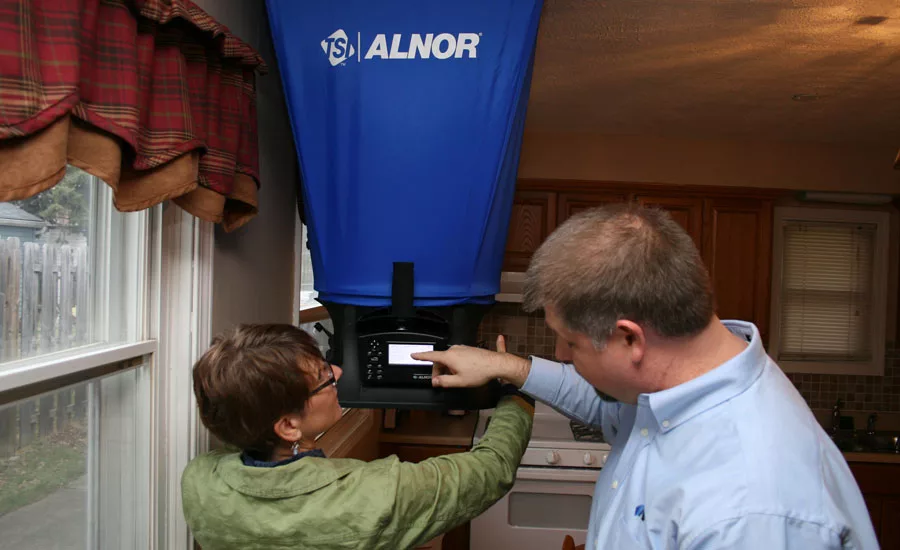
ENGAGE THE CUSTOMER: Include homeowners in room airflow estimation and measurement to help them better understand the cause of their comfort problems. A measured airflow reading that’s half of what it should be typically raises some eyebrows and generates further interest in your solutions.
Several months ago, I wrote a Duct Dynasty article titled “Four Steps to Start Optimizing a Poorly Performing Duct System.” Since then, I’ve received numerous requests to expand on the simple calculations I mentioned that can help you estimate room airflow with a customer’s input.
National Comfort Institute Inc. (NCI) created this method as a tool to help customers understand the amount of airflow needed to properly heat or cool a room. It engages them in the custom design of their system and allows them to look at the equipment as a solution to comfort problems.
When combined with a quick airflow reading from a balancing hood, the number takes on deeper meaning. A customer who sees the balancing hood reading only 35 percent of what they calculated immediately understands why their comfort has suffered and looks to you for the answer. Let’s look at how to estimate room airflow in six steps.
STEP ONE
Create a floor plan: Before you can estimate room airflow, you’ll need some measurements of the building and a duct sketch. The floor plan should include all the details you’ll need. At a minimum, it should have exterior and individual room dimensions — these are crucial to estimating airflow into each room.
Be sure to also include direction, ceiling height, door locations, room names, and grille locations.
Once the floor plan is drawn, add a sketch of the duct system for reference.
The more information you gather, the better. Record trunk, branch, and boot sizes. If the ducts are insulated, document the duct insulation rated R-value too.
Looking for quick answers on air conditioning, heating and refrigeration topics? Try Ask ACHR NEWS, our new smart AI search tool. Ask ACHR NEWS
STEP TWO
Determine required system airflow: The amount of required airflow a system needs depends on various factors ranging from elevation to equipment application. For purposes of this article, I’m going to stick with the basic industry standard of 400 cfm per ton in cooling operation.
The outdoor unit model number will usually tell you the nominal tons of cooling. If you’re unsure about the tonnage, Google the model number to find the manufacturer specifications. Once you have this information, multiply rated tons times 400 to determine required cooling system airflow.
To keep these calculations simple, you can also use the NCI Required Fan Airflow Quick Reference to easily figure the airflow needs of the equipment you’re testing. If you would like a PDF copy, send me an email request at the address at the top of the page.
STEP THREE
Determine the average supply cfm per square foot of the home: This is accomplished by dividing required system airflow (from step two) by the occupied square feet of the home (from step one).
Let’s say you have a 2-ton cooling system in a 1960s ranch home that is 1,000 square feet with 8-foot ceilings. To determine the average supply cfm per square foot, begin by multiplying the tonnage of the outdoor unit by 400 cfm per ton.
2 tons x 400 cfm per ton
= 800 cfm system required airflow
Next, you’ll need to divide the required system airflow by the occupied square feet of the home. This home has 1,000 square feet of occupied space.
800 cfm ÷ 1,000 square feet
= .8 cfm per square foot
Once you have this value, write it down; it is used to estimate the base supply cfm per room in the next step.
STEP FOUR
Determine base supply cfm: As you begin to estimate a base supply cfm for each room of the home, number each supply register on the floor plan.
Begin with the register farthest away from the equipment and move back toward the air-moving equipment. Supply registers are numbered 1, 2, 3, etc.
Next, number each return grille in the same manner, but place an “R” before each number. They are numbered as R1, R2, R3, etc.
Base supply cfm per room is estimated by multiplying the square footage of the room times the average supply cfm per square foot. To make it easier as you go along, round your base supply cfm values to end in zero or five.
Let’s say we have a living room that is 16-by-14 feet. This equals an area of 224 square feet.
For this room, the math would appear as follows:
224 square feet x .8 cfm per square foot = 179.2 cfm
To keep things simple, round to 180 cfm. If the room had two supply registers, the base supply cfm would be divided between the two registers to determine individual supply register airflow. Since the living room needs a base total of 180 cfm, each supply register should have 90 cfm.
Once you have the first room completed, continue establishing the base supply cfm for each room in the home.
| ROOM NAME | OUTLET NUMBER | ROOM SQUARE FEET | BASE SUPPLY CFM | +/- CFM | ESTIMATED CFM | MEASURED CFM |
| Living | 1 | 224 | 180 | +20 | 200 | |
| Kitchen | 2 | 156 | 125 | 125 | ||
| Laundry | 3 | 50 | 40 | +5 | 45 | |
| Master Bed | 4 | 260 | 105 | 105 | ||
| Master Bed | 5 | 260 | 105 | 105 | ||
| Bath | 6 | 49 | 40 | 40 | ||
| End Bed | 7 | 110 | 90 | +25 | 115 | |
| Middle Bed | 8 | 80 | 65 | 65 | ||
| 750 | 800 | |||||
| +50 | 50 | |||||
| Hallway | R1 | Whole House | 800 | |||
TABLE 1: This table shows an example of how adjustments look and are made to the system. If you would like the report this table comes from and the procedure on how to use it, email davidr@ncihvac.com.
STEP FIVE
Adjust Base Supply cfm: Once the base supply cfm for each room has been calculated, add the airflow amounts from each register together. The total airflow will need to be compared against required system airflow. Any variations in cfm will need to be accounted for in the adjustments.
Let’s say the base supply cfm total is 750, but required system airflow is 800 cfm. You still need to account for 50 cfm to properly distribute the amount of air the fan needs to move.
In Table 1, you can see an example of how adjustments look and are made to the system. If you would like the report this table comes from and the procedure on how to use it, send me an email request.
Adjust the base supply cfm up or down for each register depending on the conditions in each room. Don’t forget to ask your customers how much air they would like in the room. Their level of comfort will help dictate where they want air going. This is a game changer — no one else can offer this service to them. The amount of airflow improvement is verified through testing once duct upgrades are finished.
Airflow Additions to Consider:
- South and west facing rooms;
- Two or three exterior walls;
- Heat from electronics;
- Home offices;
- Large windows;
- Skylights;
- Long duct runs; and
- Vented fireplaces.
Airflow Deductions to Consider:
- Basements — also prime candidates for zoning;
- Interior rooms; and
- Closets.
STEP SIX
Determine return airflow: Once supply register airflow has been estimated, determine airflow for each return grille.
Divide the supply register airflow between return grilles by adding together the cfm of the supply registers that are served by that return grille. The goal is to have identical supply airflow and return airflow into an area of the building that can be isolated with doors. While this is not always possible, you need to assign supply register airflow to a return grille. In this step alone, you’ll often see the need for additional duct system repairs to achieve proper comfort levels in the home.
If outside air is brought into the system, deduct the amount of required outside air from the total return air amount needed at the grilles. Otherwise, you’ll have more return air than system required airflow.
CONSIDERATIONS
It’s important to remember the NCI room airflow estimation method is intended to distribute the required airflow of the equipment among rooms for diagnostic testing with a customer. It is not intended to verify proper size of the installed equipment or to replace a load calculation.
If you believe an existing system is oversized, perform a load calculation and then use the preceding steps to estimate room airflow based on properly sized equipment. An oversized system could create additional problems if a duct system is improved and equipment capacity continues to be ignored.
ENGAGE THE HOMEOWNER
Once room airflow values are estimated, measure delivered airflow from all supply registers and return grilles with a commercial-grade air balancing hood. This is the only way to know which ducts work and which don’t. And to really get your customer involved in this portion of testing, encourage them to measure airflow with the balancing hood, especially in problematic rooms.
When you have all room airflow measurements, compare measured room airflow with estimated airflow to diagnose the system.
This is where the rubber meets the road.
In this single comparison, your customer will understand why the comfort in certain rooms has been so poor. They also realize you’re the only one with the skills and knowledge to correct it.
Let everyone else continue to sell silver bullets while you advance to providing real solutions by following these six simple steps.
Publication date: 5/28/2018
Want more HVAC industry news and information? Join The NEWS on Facebook, Twitter, and LinkedIn today!
Looking for a reprint of this article?
From high-res PDFs to custom plaques, order your copy today!


