Set Outside Airflow with Fan Law Two
Adjusting outdoor duct just requires a little math
Ventilation is getting a lot of attention right now. You may have noticed that more HVAC systems include outside air for ventilation purposes. If you’ve ever encountered one of these installations, how do you know the system has the correct amount of outside air?
With two airside measurements and a little math, you can test and even adjust an outside air duct in a few minutes. Now, let’s look at how you can do this using a formula called Fan Law Two.
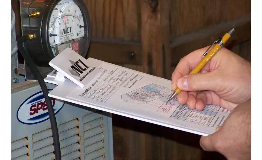
Test Instruments and Accessories
Before you can test, you’ll need the right test instruments and accessories. There are multiple ways to get the readings you need to test and adjust outside airflow.
My favorite method is to use a hot-wire or thermal anemometer and a manometer. To keep the meters straight, anemometers measure air speed and manometers measure air pressure.
If you don’t have these two test instruments, buying them is the first place to start. Here’s a brief list of additional items you will need:
- Static pressure tip
- 3/16-inch pressure tubing (silicone or neoprene work great)
- Cordless drill with a 3/8-inch drill bit or step bit
- 3/8-inch test port plugs
- Tape measure
Ready to test? Well, not yet. Once you have your test instruments, you need to know design airflow to compare your measurements against.
Gather Design Outside Air Information
The first step in the outdoor air setup can be the most confusing and challenging. Different places and applications have a variety of ventilation rates. However, ASHRAE Standards 62.1 and 62.2 are the most widely referenced.
You will also need to reference your local codes and other sources such as mechanical and energy codes. It all depends on what jurisdiction you’re working in. If you’re lucky, there are mechanical plans with the ventilation rates already specified on them.
Looking for quick answers on air conditioning, heating and refrigeration topics? Try Ask ACHR NEWS, our new smart AI search tool. Ask ACHR NEWS
Nevertheless, there will be times when you’re on a retrofit job with no specifications. In these situations, you need to figure it out for yourself. If you’re stuck, you can go with 15 cfm per person. This was the standard for many years and one that contractors still refer to because it’s simple. If you must use this value, include a note in your report that it is only a default value.
If you’re dealing with a residential building, the 15-cfm default value is per bedroom. Also, allow 30 cfm for the master bedroom since there will probably be two people in it. To illustrate, a three-bedroom home would need around 60 cfm (15 x 4 = 60 cfm). Whatever outside airflow value you use, be sure to write it down. You’ll need it later for the Fan Law Two formula.
Install Test Ports
Next, measure airflow and static pressure in the outside air duct. Unless the duct already has test ports in the correct location, you must install them. For more information about where to install test ports and how to perform the duct traverse measurement that I refer to in the next step, check out Demystifying the Duct Traverse.
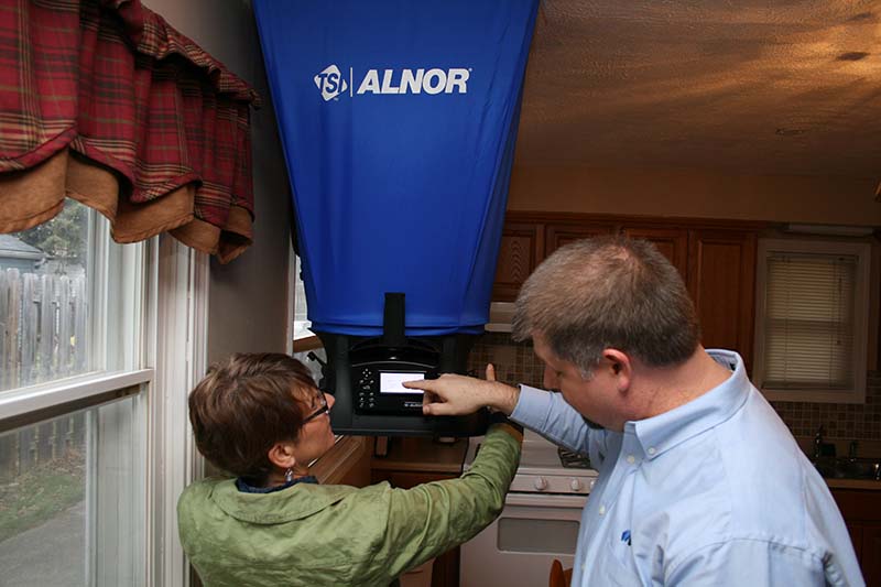
Measure Outside Airflow
Now it’s time to measure the outside air duct. You will use the anemometer to perform a duct traverse for this part of the procedure. Insert the anemometer probe into the outside air duct through the test ports.
You may encounter outside air ducts with controls that regulate outside air. Assure the airflow settings, meet design values and then let the control do its job.
Next, measure multiple air velocity readings inside the duct. If you’re traversing a rectangular duct, you will measure between 16 to 64 readings. A round duct requires between 12 to 20 readings.
To illustrate, let’s say you’re testing an air handler that serves a conference room. There is an eight-inch round outside air duct designed to provide 150 cfm of airflow. Write this value down. It’s an important part of the Fan Law Two formula you will use later.
Next, install test ports in the outside air duct and then traverse it with the anemometer. Most anemometers let you program the duct dimensions, so the instrument performs the airflow calculations. If you’re like me, you’ll let the instrument do the math.
After your traverse is complete, you notice the anemometer displays a measured outside airflow of 180 cfm. That isn’t a typo. You have more airflow than you need! Also, write this value down. That finishes the initial airflow part of the test. One more measurement and you’ll have all the information you need.
Measure Static Pressure
In this step, measure and record static pressure from one of the test ports that you took your traverse measurements in.
First, turn on your manometer and zero it. Next, attach a static pressure tip and tubing to the manometer. Insert the static pressure tip into the test port and read the static pressure on the manometer display.
This is the last piece of information that you’ll need for Fan Law Two and to make your adjustments. Leave the static pressure tip inserted in the duct and your manometer on. You will need it once you complete your calculations.
Building on the previous example, you measure static pressure in the 8-inch duct and find that it is .12-in. w.c. (inches of water column). Write this final measurement down and get your calculator ready for Fan Law Two.
Fan Law Two Basics
Fan Law Two shows us that static pressure changes at the square of airflow, or pressure changes a little more than twice the airflow rate. For example, let’s say you increase fan airflow 10 percent. This would equal an approximate static pressure increase of 21 percent.
As you continue, you’ll notice that you divide once and multiply twice when you use the fan law formula.
The Fan Law Two formula is:
(CFM2 ÷ CFM1)2 x SP1 = SP2
Where:
- CFM = cubic feet per minute, or airflow
- SP = Static Pressure
Each abbreviation in Fan Law Two has a subscript number one (1) or two (2) at the bottom right. An abbreviation with one (1) next to it shows the measured or known value in the formula. It is typically your initial field measurement. In some fan law variations, the one (1) below the value is referred to as the “old” value.
An abbreviation with two (2) next to it shows the design value. It is the measurement in the formula you’re solving or trying to achieve. In some fan law variations, the two (2) below the value is referred to as the “new” value.
The parentheses in the formula show that you need to, “Do this part of the formula first.” In our example, CFM2 is the design airflow and CFM1 is the measured airflow.
When you see the superscript number two (2) outside the parentheses, at the upper right-hand side, you need to square your answer from inside the parentheses. To square a number, you multiply it by itself. For example, if you square the number four, it equals 16 (4 x 4 = 16).
Plug Your Airflow and Static Pressure Into Fan Law Two
Up to this point you have taken two measurements in the outside air duct and located the design airflow the duct should have. Those values are:
- 150 cfm (design airflow)
- 180 cfm (measured airflow)
- .12-in. w.c. (measured static pressure)
Next, we’ll put those readings into Fan Law Two and calculate the static pressure reading we should see in the outside air duct when it has 150 cfm moving through it:
- CFM2 = 150 cfm (the design airflow)
- CFM1 = 180 cfm (the measured airflow)
- SP1 = .12 in. w.c. (the measured static pressure)
- SP2 = ?? in. w.c. (the static pressure you’re aiming for)
Now let’s take the Fan Law Two formula and place all the numbers from above into it. To keep the answers short, I’m going to round them.
The formula now looks like this:
(150 ÷ 180)2 x .12 = SP2.
First, divide CFM2 (150) by CFM1 (180) to determine the ratio of airflow decrease. 150 divided by 180 equals .83, or a 17 percent airflow decrease.
.832 x .12 = SP2
Next, square this number by multiplying .83 by itself (.83 x .83), which equals .69.
.69 x .12 = SP2
Finally, multiply the outside air duct measured static pressure, or SP1 (.12) by .69 to determine SP2, or the static pressure you’re aiming for.
.08 in. w.c. = SP2
This is the static pressure reading you should measure in the outside air duct with 150 cfm moving through it.
Adjust the Volume Damper
In the next step, adjust the outside air ducts volume damper until your manometer displays the static pressure you calculated with Fan Law Two in the previous step. You can do this quickly and it’s the reason I recommended you leave the manometer setup for this part.
As we continue our example, you calculated .08 in. w.c. as the static pressure reading that would occur if there is 150 cfm moving through the outside air duct. You have a static pressure reading of .12 in. w.c. at 180 cfm.
Slowly shut the volume damper in the outside air duct as you watch the display on your manometer. Once it reads .08 in. w.c., you have the damper set and the proper amount of airflow through the duct. There’s one more verification step and you’ve successfully adjusted an outside air duct.
Retest Outside Airflow
In the last step, you need to do one more duct traverse and compare it against design airflow. An outside air duct’s airflow should be at design airflow or up to 110 percent. Do not set the outside air value below design values.
In the example, you perform a second duct traverse and find the airflow through the outside air duct is 156 cfm. This is within 10 percent of the design range of 150 to 165 cfm.
The key with this adjustment is control and knowing what to aim for. If you have too much outdoor air, you can turn the volume damper down. If you don’t have enough, you can open the damper up, assuming the outside air duct can provide enough airflow. That brings in some fun scenarios.
Field Challenges
The party begins when the outside air duct is undersized or poorly installed. It will need some form of repair to provide the right amount of air. Also, don’t forget the missing volume damper — it’s hard to control air without one.
I hope you enjoyed this overview of how you can adjust airflow with Fan Law Two. I would encourage you to look at other applications where you can use this technique. It has saved me when suspended ducts and exhaust ducts were a challenge to measure. If you would like a one-page sheet of the most common fan law variations, send me an email to request a PDF copy.
If you're an HVAC contractor or technician interested in learning more about fan laws, contact me at davidr@ncihvac.com or call 800-633-7058. NCI’s website www.nationalcomfortinstitute.com is full of free technical articles and downloads to help you improve your professionalism and strengthen your company
Looking for a reprint of this article?
From high-res PDFs to custom plaques, order your copy today!


