Heat Pump Electrical Component Checks
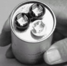
Capacitor Electrical Check
Caution: Any capacitor showing signs of leaks or bulging must be replaced immediately. Do not operate the compressor with a capacitor showing these signs.Single-phase compressors require a run capacitor connected to the run and start winding. This puts the two windings out of phase from one another and allows the compressor motor to start.
The best method of checking a capacitor’s integrity and capacitance is to use a quality capacitor analyzer. A capacitor analyzer can measure the capacitor dielectric and determine if the MFD value is proper or has deteriorated. If a capacitor analyzer is not available, use a quality analog ohmmeter to check the resistance between the capacitor plates.
1. Warning: Disconnect electrical power before performing this test. Failure to do so can result in electrical shock causing personal injury or death.
2. Set the ohmmeter to the highest scale available.
3. Discharge the capacitor by shorting the terminals with a 2-watt 20,000-ohmï€ resistor.
4. Place the ohmmeter probes on the capacitor terminals and read:
A. The meter pointer moves toward zero, then gradually moves to higher ohm values. The capacitor is good.
Looking for quick answers on air conditioning, heating and refrigeration topics? Try Ask ACHR NEWS, our new smart AI search tool. Ask ACHR NEWS
B. The meter pointer does not move. It is an open capacitor - replace.
C. The meter pointer goes toward zero ohms and stays. It is a shorted capacitor - replace.
5. Replace any failed capacitor with a capacitor having the same MFD and voltage rating.

Compressor Start Kits
Some compressors require the assistance of an additional capacitor to start. This capacitor is taken out of the circuit as soon as the compressor reaches about 75 percent of its running rpm. The potential relay opens a circuit to the start capacitor.Important: Only use factory specified start kits. Using an improper start kit can cause premature compressor failure.
The potential relay uses three terminals: 1, 2, and 5. The normally closed contacts are between terminals 1 and 2. The relay coil that opens them is between terminals 2 and 5.
Start Kit Connections
1. One terminal of the start capacitor connects to line power going to the compressor Run terminal.
2. Relay terminal 1 connects to the other start capacitor terminal.
3. Relay terminal 2 connects to the compressor Start terminal.
4. Relay terminal 5 connects to the load side of the compressor contactor going to the compressor Common terminal.
Start Kit Operation
Immediately on starting, the start capacitor assists the run capacitor to turn the compressor motor. As the motor comes up to speed a voltage builds in the compressor start winding. When the motor reaches approximately 75 percent of its running rpm, the start winding voltage energizes the coil between potential relay terminals 2 and 5. This coil then opens its normally closed contacts 1 and 2. The start capacitor is now isolated from the compressor. A small bleed resistor between the start capacitor terminals discharges the capacitor making it ready for the next start.
Start Kit Electrical Checks
Warning: Disconnect all power to the outdoor unit before beginning this test. Servicing the unit with electrical power on can result in electrical shock, serious injury, or death.
1. Check the start capacitor using the same method as with a run capacitor. (First remove the bleed resistor.)
2. Measure the resistance between potential relay terminals 1 and 2. There should be zero ohms.
This indicates the contacts are properly closed. If there is infinite resistance, the contacts are open and the relay must be replaced.
3. Measure the resistance between the potential relay holding coil terminals 2 and 5. Use a higher ohm scale. There should be several thousand ohms resistance. If there is infinite resistance, the coil is open and must be replaced. Less than 1,000 ohms indicates a coil short.
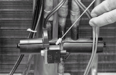
Reversing Valves
Electrical OperationThere are two valves in the reversing valve assembly. The solenoid or pilot valve is energized by 24 volts when the thermostat mode is set to heating operation. The slide valve is positioned by the pilot valve. Use the ohmmeter to check the 24-volt pilot solenoid. Do not energize the solenoid without the reversing valve pilot stem in place in the coil. Excessive current results in causing coil failure.
Electrical Check
1. Put the thermostat into the cooling mode (into the heating mode for Rheem/Ruud products).
2. Measure the voltage at the solenoid wiring connections. There should be approximately 24 volts.
A. If there is no voltage, check for 24-volt power at the indoor transformer.
B. If there is 24 volts at the transformer, check the thermostat and the wiring circuit going to the reversing valve.
3. If there is 24 volts present and the solenoid is intact, place a knife blade or unmagnetized screwdriver blade at the end of the solenoid. The solenoid should magnetically pull at the blade.
A. If there is no magnetic pull, use an ohmmeter to determine if there is electrical resistance in the solenoid coil.
B. Remove the wires attached to the solenoid and measure the resistance.
C. Normal solenoid resistance should be 10-60 ohms.
D. If the solenoid has failed, remove the nut at the end, slide the solenoid from the shaft, and replace with another solenoid.

The second part of the reversing valve assembly is a pressure operated slide valve. The pilot solenoid valve directs refrigerant pressure to move the slide assembly in the valve body. The position of the slide valve directs system refrigerant flow to produce heat or cooling at the indoor coil.
A sticking slide valve is the most common problem in reversing valves. This is most often caused by contaminants in the valve body caused by using unclean refrigerant lines, or excessive flux and solder material.
Reversing valves that internally leak also cause problems but are rare. A temperature check at the tubes with an electronic temperature tester usually indicates this fault.
Determine the two tubes on the valve carrying cold suction gas. In cooling they are the center and the one connected to the indoor coil. In heating they are the center and the one connected to the outdoor coil.
Mechanical Check
1. Locate the correct refrigerant tubes leaving the reversing valve.
2. Measure the tube temperatures about 2 inches from the valve body.
A. If the temperature difference is within 4 degrees, the valve is not leaking.
B. If the reading is 10 degrees or more, there is a good chance the valve is leaking internally.
3. If the valve has failed, remove the solenoid, recover the refrigerant, and unsolder the valve body.
4. Wrap the new valve body with wet rags or heat sink material, and carefully braze the new valve body in place.
5. Replace the solenoid onto the new valve body.

Motors
ElectricalThe motors in both the outdoor and indoor units are similar. Outdoor motors have one speed while indoor motors usually are multispeed. Most fan motors require a capacitor for the best torque and efficiency. If the motor is replaced, replace the capacitor.
The fan motor has both "Run" and "Start" windings. Extended run windings furnish a choice of speeds with indoor products. Use an ohmmeter to troubleshoot motors.
Electrical Checks
1. Be sure power is off to the motor.
2. Disconnect the motor wires.
3. Place one ohmmeter lead on Common and the other on Start. The meter should show resistance.
4. Place one ohmmeter lead on Common and the other lead to Run. The meter should show less resistance.
5. Leave ohmmeter lead on Common and touch each remaining lead. Each should indicate resistance.
6. If a winding does not show resistance, the motor has failed and must be replaced.
7. If the motor needs replacing, replace the capacitor as well.
Mechanical
Fan motors can suffer a bearing loss due to a lack of lubrication. This may be caused by excessive water spilling from a roof above the unit. Lubrication can be washed out of permanently lubricated motor bearings. Over-lubrication causes dirt to stick to oiling ports and can contaminate the bearings. If a motor fails, replace it with a motor having the same rotation and electrical characteristics.
Note: When parts combination results in motor/blade interference, the fan blade should be located to provide 1/8-inch motor/blade clearance.

Relays
Electrical OperationRelay coils are wires wound around an iron core. When energized a coil becomes a magnet opening or closing contacts that make or break electrical circuits. Electrical continuity indicates a good coil. Relay coils use specific voltages. Using the wrong voltage either destroys the relay or it just doesn’t operate. Avoid this by using the proper replacement part for a failed component.
Relay contacts are switches and can become pitted or corroded, creating resistance. Corrosion can generate enough heat to weld the contacts together. Physical examination of the contacts shows this problem. With sealed relays, use an ohmmeter to show open or closed contacts.
Electrical Checks
1. Be sure all electrical power is off to the component being checked.
2. Remove at least one wire from the component being checked.
3. Measure the resistance of the holding coil with an ohmmeter.
A. A specific resistance indicates a good holding coil.
B. Infinite resistance indicates a relay with an open holding coil. Replace this relay with an identical part.
4. Measure the resistance across the normally closed (NC) relay contacts.
A. The resistance should be zero ohms.
B. If the resistance is more than 0.2 ohms the contacts are pitted. Replace this relay with an identical part.
5. Measure the resistance across the normally open (NO) relay contacts.
A. The resistance should be infinite.
B. If the resistance is less than infinite, replace with an identical part.
Mechanical Checks
In relays, mechanical faults are few, with the exception of physical damage.
High-Pressure Control (HPC) Switch
The high-pressure switch shuts down the outdoor unit if excessively high head pressures occur. The switch is a 24-volt control and is wired in series with the compressor contactor. If it opens, it breaks power to the contactor and stops the outdoor unit.Important: If the high-pressure switch is open, determine the cause, when possible, before resetting the control.
High-Pressure Switch Checks
If the high-pressure switch opens the probable cause is an overcharge, dirty condenser coil, faulty or wrong size condenser fan motor, faulty fan blade or wrong rotation, recirculation of condenser air, additional heat source, noncondensibles, or equipment not matched.
Hot Gas Sensor Control (HGS)
The hot gas sensor shuts down the outdoor unit if excessively high discharge gas temperatures occur. The switch is a 24-volt control and is wired in series with the compressor contactor. If it opens it breaks power to the contactor and stops the outdoor unit.Its function is to detect loss of refrigerant charge in the system. If the system is low on charge, the remaining suction gas must still cool a large compressor motor. The remaining gas temperature rises as it attempts to cool the large compressor motor.
Hot Gas Sensor Checks
If the hot gas sensor switch opens the probable cause is a low charge or refrigerant leak.
Reprinted with permission from the Residential Split System Heat Pumps service manual from Rheem Air Conditioning Division, Fort Smith, Ark. For more information, visit www.rheemac.com.
Publication date: 01/10/2005
Looking for a reprint of this article?
From high-res PDFs to custom plaques, order your copy today!


