Screw Compressor Teardown: A Few Basics - Part 1
First, let’s cover some background on screw compressors.
History Of The Screw Compressor
The early principle design of the screw compressor was first patented in Germany in 1878. In 1935, a compressor design using four male lobes and five female valleys was patented and is considered the birth of the modern screw compressor. The company making the patent changed its name in 1951 to SRM. Today SRM is known worldwide for its screw compressor and rotor knowledge and has issued manufacturing agreements to almost every screw compressor manufacturer that exists today.What Is A Screw Compressor?
A screw compressor is a positive displacement volume reduction machine in which compression is achieved by the enmeshing of two helical grooved rotors positioned in a tight tolerance housing fitted with an inlet and outlet port.Types Of Screw Compressors
Screw compressors can be either twin helical screws or a single screw design. They can be open drive, semi-hermetic, or hermetic in configuration. In addition, there are oil-flooded compressors and non-oil (dry) compressors. Screw compressors are designed to work in a wide variety of applications including, but not exclusively limited to, refrigeration, comfort cooling, open loop gas processes, and air compression.How It Works
Compression occurs by the intermeshing of screws between tight tolerance housing bores. As the rotors turn in opposite directions, gas is drawn into the rotors through the inlet port and fills the compression pocket (thread) located between the male lobe and female rotor flute. The initial volume of gas is referred to as suction volume.As the screws continue to rotate, the gas becomes trapped between the compressor housings and rotors and is moved axially and radially through the rotor housing. The compression cycle begins when the gas filled thread is closed off from the suction port. Additional intermeshing of the lobes results in the reduction (compression) of the initial suction volume of gas until the gas is released through the outlet port. Compression discharge is determined by the location of the outlet port.
To provide a better understanding of the compression process, the following illustrations compare the compression of gas in a reciprocating compressor to the compression of gas in a screw compressor.

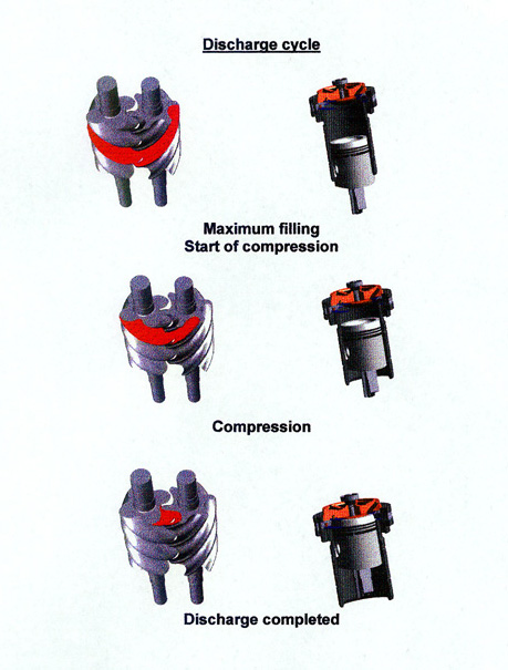
The illustration below represents a compressor with a slide valve and a moveable slide stop. There are two discharge ports, the radial port located on the slide valve and the axial port located in the discharge housing.

What’s On The Outside
Various ports are located throughout the exterior of the compressor. Standard ports such as oil supply to the shaft seal, balance piston, and main oil injection are used on nearly all oil-flooded compressors. Other ports are used for liquid refrigerant injection for oil cooling as well as a vapor return port (economizer) used to pull on a second evaporator. Electronic devices to monitor the position of the slide valve and slide stop, if available, are also affixed to the compressor.What’s On The Inside
Unlike reciprocating compressors, screw compressors are fairly limited in the amount of internal components they contain. Major internal components would consist of the following.
Bearings:
As the gas is compressed along the length of the rotors, the rotors are forced in the radial and axial directions. To maintain rotor position, two types of bearings are used. Bearings are identified as ball thrust bearings and journal bearings.
Thrust bearings are required to control the axial (back and forth) movement of the rotors. Two designs that are typically used are the single angular contact and the four-point contact bearing. Single angular contact bearings are designed to take a load in only one direction; therefore two identical bearings are used and positioned back-to-back to control the axial force in both directions. The four-point contact bearing is designed to take the axial force in both directions. One four-point contact bearing takes the place of two single angular bearings.
Radial bearings are used to maintain the (up and down and sideways) movement of the rotors. Two of the most common bearings used today are the sleeve bearing design and the cylindrical roller design. Sleeve bearings utilize a sleeve placed in the compressor housing that runs against the rotor shaft. The design of the sleeve bearing requires the oil supplied to the bearing to be free of gas bubbles. Gas bubbles entering the bearing will collapse and allow the bearing to go metal-to-metal resulting in a bearing failure. To obtain a solid column of oil, a pump is used to raise the oil pressure over discharge pressure to eliminate the flashing of refrigerant in the oil supply. Typical oil pressure is approximately 25 psig higher than discharge pressure.
The roller bearing, also referred to as an anti-friction bearing, is a precision component consisting of cylindrical rollers, cage, inner ring/raceway, and outer ring/raceway. The cage is secured in the outer race and maintains the position of the rollers. The outer race is fitted snugly in the compressor housing whereas the inner race is secured to the rotor shaft by interference fit. As the shaft rotates and radial forces occur, the load is transmitted from the inner race, through the rollers and into the outer race. Lubrication is required to avoid metal-to-metal contact between components and to reduce excessive frictional heat.
Looking for quick answers on air conditioning, heating and refrigeration topics? Try Ask ACHR NEWS, our new smart AI search tool. Ask ACHR NEWS
Unlike the sleeve bearing that requires bubble-free oil between the two sleeves, roller bearings are not affected by gas bubbles in the oil. The anti-friction bearing rolls over the foam and collapses the gas bubbles out of the oil, leaving a solid oil supply to the oil reservoir in the bearing cavity. Because anti-friction bearings are effective with foamy oil, the need for a full-time pump to raise the oil pressure over discharge is eliminated. Oil is forced in the bearing cavities through differential pressure rather than by a pump. Many compressor units on the market today are sold with only pre-lube pumps or no oil pumps.
Balance piston:
As previously mentioned, thrust bearings are installed on each rotor to hold the rotor against axial forces. The higher the gas load force applied to the rotor, the greater the force that is applied to the thrust bearing. To help offset the axial load of the thrust bearing, a balance piston is installed on the rotor. The balance piston’s function is to extend the operational life of the thrust bearing.
Typically, a balance piston is of a two-part design consisting of a rotating piston and a stationary sleeve. The piston, designed with a labyrinth seal on the OD, fits snugly into the balance piston sleeve with a very small clearance between each component. High-pressure oil is supplied to the piston resulting in an opposing force on the rotors, eliminating some of the axial load applied to the thrust bearing. Again, depending upon the compressor manufacturer, balance pistons can be located on the male rotor, female rotor, or both.
Shaft Seals:
Because of the open drive design, a shaft seal is required to prevent oil and gas leakage from occurring around the drive shaft. This is also the component that draws the most attention. Shaft seals can be as simple as a standard carbon assembly and mating hard face metal seat, to elaborate designs such as tandem and compound seals. Typically, the refrigerant and the application of the system determine the type of seal used.
A high percentage of applications use the standard carbon seal mating with a hardened metal seat. The carbon can either be stationary (non-rotating) or attached to the rotor (rotating). Due to the shaft seal being flooded with oil, some oil leakage during operation is considered normal. A tandem seal is designed to prevent any type of leakage to the atmosphere.
Capacity Control
There are a number of capacity control methods used in screw compressors throughout the industry. A few are:Volume Ratio (Vi) Slide Stop
In reciprocating compressors, the discharge valve opens when the gas pressure in the cylinder bore exceeds the pressure upstream of the discharge valve. Screw compressors do not have discharge valves; therefore the location of the discharge port determines the maximum discharge pressure that can be obtained before the gas is released to the discharge piping.What must be considered when applying a screw compressor in a system is the comparison of the internal volume ratio of the compressor to the volume ratio of the system. The comparison of the volume of trapped gas at suction (Vs) to the volume of trapped gas remaining in the thread pocket prior to release to discharge piping (Vd) is the internal Volume Ratio. The Vi or Volume Index determines the compressor’s pressure ratio.
Therefore: Vi = Vs/Vd.
The evaporator determines the suction pressure entering the compressor; the discharge port of the compressor determines the pressure that will be released. The discharge pressure may or may not match that of the system’s discharge pressure depending upon the location of the discharge port. If the internal volume ratio is too high for a given set of operating conditions, the gas will be trapped for a longer period of time and the pressure will rise above the system’s discharge pressure. This is referred to as over-compression and results in increased energy usage. A graph representing over-compression is shown in Figure 1.

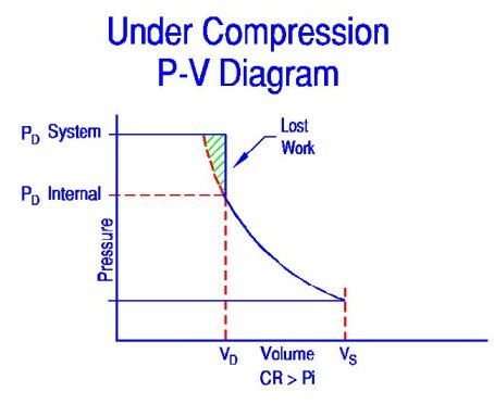
The other end of the spectrum is when the internal volume ratio is lower than what is required for the operating conditions. This is referred to as under-compression. The gas is released at a lower pressure than what is in the discharge piping. The higher system pressure flows back into the rotors and increases the thread pressure to the higher pressure. The compressor now has to pump against the higher pressure. Just as in over-compressing, under-compressing results in excessive energy usage. A graph representing under-compression is shown in Figure 2.
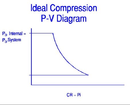
It is ideal when the internal volume ratio matches the system’s volume ratio. A diagram representing ideal compression is shown in Figure 3.
Fixed Vi
Fixed volume ratio compressors are designed to operate in a specific range of operating conditions. Because the Vi is fixed, maximum efficiency is achieved when the compressor operates within the design parameters. Once the compressor operates outside the design parameters, the efficiency drops due to over-compression and under-compression of the gas. Some compressors used for particular applications in which the system’s conditions are fairly consistent use the fixed Vi design. Examples would be booster applications and comfort air chillers.Variable Vi
Some of the most efficient compressors used in the industry are those that are equipped with a variable Vi. These compressors have both a movable slide stop and a movable slide valve. Capacity of the compressor is controlled with the slide valve as discussed in the capacity control section, whereas the internal volume is determined by the slide stop. Discharge and suction pressures determine the position of the slide stop. The variable slide stop is designed to travel in conjunction with the slide valve. As the slide stop moves, and with the slide valve at the 100% position, the discharge port on the slide valve is relocated. Relocating the discharge port changes the internal volume of the rotor thread, preventing the compressor from under-compressing or over-compressing the refrigerant gas.The moving of the slide stop can either be performed manually or automatically. To control the slide stop manually, an operator determines the Vi position by using a chart outlining the calculations. The operator then moves the slide stop by opening and closing valves. In a manually controlled system, the Vi is typically limited to several different positions. To move the slide stop automatically, a computer or microprocessor is programmed to constantly calculate the slide stop position by monitoring the suction and discharge pressures. Once a change is needed, the processor calculates the desired location and moves the slide stop by the use of hydraulic pressure. The variable slide stop is designed to typically travel from a 2.2 Vi position to a 5.0 Vi position.
Figure 4 shows how a variable Vi compressor can relocate the radial discharge port on the slide valve to avoid under- and over-compression of the gas.

Part Two of this series will discuss screw compressor maintenance.
Yoder is a service technician with York Refrigeration/Frick in Waynesboro, Pa. For more information, visit www.yorkref.com.
Publication date: 02/24/2003
Looking for a reprint of this article?
From high-res PDFs to custom plaques, order your copy today!


