Duct Dynasty
Clearing the Air Surrounding Air Handler Static Pressure Measurements

To test air handler static pressure, understand the components included in the equipment, and follow proven procedures.
Measuring total external static pressure (TESP) on an air handler can be confusing. It’s even worse when you’re the one who is adding to the confusion.
A recent email from Judy Rachel, with Home Performance Pro, pointed out how the illustration I used in a 10-year-old article showed the wrong test locations. She was 100% correct. The illustration showed testing air handler TESP with a manufacturer-installed air filter. These test locations were incorrect for the article’s context and didn’t line up with the previous training Judy received from National Comfort Institute (NCI). Naturally, it raised a red flag for her.
For decades, NCI has taught treating air filters as external components when measuring TESP. It’s a way to simplify the measurement. Judy’s email exposed a problem that has existed in our industry for a long time — manufacturers don’t follow a consistent method in their air handler TESP ratings. One approach doesn’t work for all air handlers.
My heart sank when Judy told me that someone was using this incorrect illustration in a training class she attended. I don’t know how many technicians I negatively affected by accidentally choosing the wrong illustration, but this article is my attempt to clarify any confusion I unknowingly helped create. Let’s look at air handler static pressure testing and how we can clear up confusion surrounding it.
So, What’s Included?
Before you test air handler static pressure, it’s a good idea to understand the components included in the equipment. For this article, I’ll focus on single-piece air handlers because they make up most of what you’ll see on residential jobsites.
If a component isn’t inside the air handler, like the duct system, it’s an external component. A concept we use at NCI to help students understand where to measure TESP is called “as-shipped.” To apply the “as-shipped” principle to an air handler, think about how it comes from the factory in the box or wrapping. When you unpackage the air handler, what’s inside? These are the components the manufacturer includes in their TESP measurement. Everything else is external.
If you have questions on what is included and what is not, you can look at the fan table footnotes for the air handler. They are in the equipment manual and tell you how the manufacturer rated that air handler.
Looking for quick answers on air conditioning, heating and refrigeration topics? Try Ask ACHR NEWS, our new smart AI search tool. Ask ACHR NEWS
Three Internal Components to Consider
There are three internal components that affect pressure in an air handler. They are the coil, the factory-shipped air filter (if so equipped), and electric heat strips (if so equipped). If you don’t understand how these internal components respond to pressure, and how manufacturers account for them, you can get inconsistent measurements and results.
The first component is the internal coil. Manufacturers include it in their air handler TESP measurements as part of the “as shipped” package. If you treat the internal coil as an external component, you will chase excessive static pressure problems that don’t exist. Because manufacturers rate the air handler with a clean coil in the laboratory, you still need to measure coil pressure drop separately. Ideally, it’s best to measure and document “clean” coil pressure drop at startup since pressure drop data for most internal coils is often unavailable. Startup may be your only opportunity to capture the clean pressure drop as a baseline for future diagnostics and maintenance.
The second internal component, and cause for this article, is a factory air filter. Some manufacturers include an internal air filter “as-shipped” in their air handlers. Although this practice is becoming less common, you need to understand the effect it can have on TESP readings. Most factory filters have a low pressure drop when clean and add little resistance to airflow. Because of inconsistent ratings, don’t include the filter in your TESP reading. Treat it as an external component.
The third component is the electric heat strip. They rarely influence pressures enough in a residential air handler to worry about them. To my knowledge, I’ve never seen a heat strip package shipped in an air handler. If you have, I would love to know! Whatever you do, don’t measure the pressure drop across the heater. You might get electrocuted trying to measure a reading that doesn’t have much value. If you’re interested in the pressure-drop number, look up the engineering data for the heat strip model and call it a day.
A Consistent Approach to Measure and Diagnose Air Handler TESP
You’ll need to install two test ports to measure pressures. The locations I’m using follow the direction of airflow through an air handler — from return to supply. The following steps are for TESP only, using two hoses and static pressure tips with the filter mounted near the air handler.
- Install a 3/8-inch test port into the duct or equipment on the exiting air side of the filter. This is your pressure measurement after the filter, just before air enters the air handler coil. If you must test-in the air handler because of an internal filter, inspect before you drill — you don’t want to drill into a drain pan.
- Install a 3/8-inch test port into the supply duct on the leaving air side of the equipment (supply plenum). This is your pressure measurement as air leaves the air handler. If you measure too close to the air handler outlet, you will get goofy readings because of turbulence.
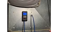
- Turn on your digital manometer, or if using an analog manometer (Magnehelic), make sure it is level and zero it.
- Attach a hose to each pressure tap of the manometer and insert a static pressure tip into the opposite end of each of those hoses. Some manometers are sensitive to hose placement on different ports and may vary from the following instructions. Review your manometer for specific directions.
- Insert the static pressure tip attached to the hose going to the (+) port of the manometer or (high) port of the Magnehelic into the 3/8-inch port you installed in the supply plenum.
- Insert the static pressure tip attached to the hose going to the (-) port of the manometer or (low) port of the Magnehelic into the 3/8-inch port you installed after the filter.
- The measured TESP reading will appear on the manometer display. Read and record it.
Ideally, the measured TESP reading should not exceed the air handler’s maximum-rated TESP. You can find this rating on the air handler data plate on the blower panel. Compare the measured TESP reading to the maximum-rated TESP. The rating for most residential air handlers is .50” w.c. (inches of water column). If the measured TESP reading exceeds .50” w.c., you could have airside problems.
Don’t Let Low TESP Fool You
There will be many instances when you see low TESP measurements and think everything is great. Don’t be fooled. Unfortunately, low TESP doesn’t always ensure there are no problems. There are hidden issues that may not show up when measuring TESP alone. Here are a few examples of issues that could hide from a TESP-only measurement.
Low fan airflow is a common source of lower-than-normal TESP readings. A dirty blower wheel is the most common culprit because it is hidden from an air handler TESP measurement. TESP readings look better than they really are because the fan is moving less air. Another issue to look for is incorrect blower speed settings. This could be from the fan speed settings being in the wrong positions or an air handler with a variable-speed fan tested in the “fan-on” position. For the most accurate results, make sure fan airflow is near 100% of what the fan should operate at.
Hidden internal pressure drops that are excessive, like a dirty internal coil or factory air filter, will also cause low measured TESP. This happens because the dirty component pressure drop is hidden within the air handler TESP measurement, just like the dirty blower wheel and restricting airflow. As the restriction through these components increases, fan airflow decreases.
It’s Time to Change Air Handler TESP Ratings
Measuring TESP on air handlers always leads to interesting discussions, especially since there are no clear and consistent rating methods among manufacturers. Is it any wonder technicians and installers resist static pressure measurements? Our industry has unknowingly turned it into a game of whack-a-mole — the target is always moving. Results show up in the number of incorrect measurements, misdiagnosed airside issues, and a false sense of security.
Manufacturers could improve these ratings to a consistent metric if they’re willing to work together. Gas furnace ratings are universal among manufacturers, so why not air handlers? My suggestion is to follow an approach that all manufacturers currently use with modular (two-piece) air handlers. Everything not included in the blower section is left out of the TESP rating. Treat each component, such as the coil and filter, as external.
This shift would simplify testing and eliminate unnecessary confusion for many technicians and designers. As our industry moves closer to heat pump adoption and electrification, a change like this is critical. With all the changes currently happening in our industry, isn’t it time we made one that simplified our jobs?
Looking for a reprint of this article?
From high-res PDFs to custom plaques, order your copy today!