Tracking Down the Cause of Compressor Motor Overheating
Voltage imbalance in three-phase system may be elusive reason for the problem

One of the more popular three-phase electrical services supplied to medium-size commercial buildings is the Wye or Star configuration transformer. The name comes from the transformer’s secondary winding configuration, which looks like a “Y” or three-sided star (see Figure 1). This dual-voltage, three-phase electrical service usually delivers four wires to the building. There are actually three 120-volt windings in the secondary of the step-down transformer, which are 120 electrical degrees apart. They consist of three hot wires and a neutral or ground (Figure 1). The secondary winding of the Wye is center tapped and grounded. This makes the center tap or ground perfectly symmetrical to all three phases of its power.
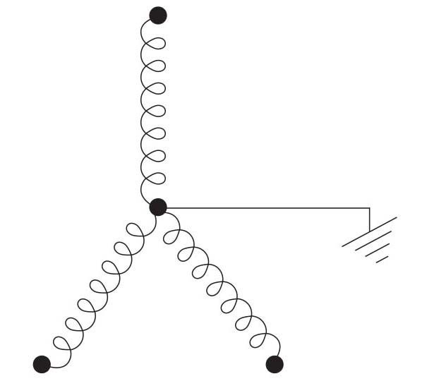
Figure 1: Wye or Star secondary winding of a three-phase transformer.
TRANSFORMER SECONDARY VOLTAGES
Wye service transformers can be used for three-phase or single-phase applications. Single-phase voltages can be picked off of the Wye secondary (see Figure 2). Listed here are those single-phase voltages:
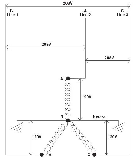
• A to B: 208 V
• A to C: 208 V
• B to C: 208 V
• A to N: 120 V
• B to N: 120 V
• C to N: 120 V
Figure 2: Single-phase voltages from a Wye or Star secondary three-phase transformer.
As can be seen, 120 V single phase, 208 V single-phase, and 208 V three-phase powers can be had from the Wye when it is center tapped to the ground. The 208 V three-phase happens when all three leads are used (A, B, and C). Remember, voltage is only measured relative to any two of the leads though. Also, if the Wye was not center tapped to ground, no low-voltage (120 V) single-phase power would be available. However, 208 V single-phase and 208 V three-phase power still would be available without the center tap. The 208 V single-phase power would come from any two power legs: A and B, B and C, or A and C (Figure 2).
It can be said that any two of the three windings of the Wye secondary are in series with one another (Figure 2). However, remember that power surges of the induced voltages that come from the primary windings of the transformer to the secondary windings are not in phase with one another. In fact, each phase is 120 degrees out of phase with one another. When one phase is positive and maximum voltage, the voltages of the other phases or windings may be negative and less than maximum. This phenomenon makes the voltage between any two conductors to be 208 volt and not 240 V (120 V x 2).
Notice that the neutral or ground wire is connected to the center of the Wye, which makes it perfectly symmetrical to all three windings. The voltage between any phase (A, B, or C) and neutral (N) will be 120 V. All 120 V single-phase loads may be connected to neutral and any of the three power phase wires — A, B, or C — without worrying about burning them out from too high of a voltage. To balance the electrical loads, all single-phase loads should be equally spread between the three secondary windings.
If the turns of wire of the secondary windings are increased, a higher voltage will be induced into them from the primary windings of service transformer. Often, each phase of the Wye transformer to neutral will deliver 277 V instead of 120 V, and the voltage between any two phases is 480 V instead of 208 V. The 277 V is often used for lighting in commercial and industrial buildings. The advantage of the higher voltage is to reduce the amperage for a given amount of power. Line losses are reduced, and wiring size can then be reduced because of the lower amperage flow. Even electric motors can be made lighter because of the higher voltage causing a smaller wire size.
VOLTAGE IMBALANCES AND MOTOR HEATING
Compressor motor overheating is one of the HVACR industry’s most serious field problems and is usually caused from high compression ratios, which can be caused from high condensing pressures (temperatures) and low suction (evaporating) pressures, or a combination of both. However, one of the more elusive causes of compressor motor overheating and failure is voltage unbalance in compressor motors. Voltage imbalance can be found with a voltmeter by measuring between phases on the compressor’s motor terminals, at the motor’s disconnect, or at the contactor or starter terminals.
As mentioned above, a more common configuration in three-phase motor windings is the Wye or Star configuration. By simply measuring voltages between line 1 to line 2, line 2 to line 3, and line 3 to line 1, and performing a few simple mathematical calculations, a service technician can determine if there is a voltage imbalance problem.
Looking for quick answers on air conditioning, heating and refrigeration topics? Try Ask ACHR NEWS, our new smart AI search tool. Ask ACHR NEWS
Voltage imbalances exceeding 2 percent in three-phase systems can cause current imbalance among the windings. These voltage and current imbalances can cause an increase in winding temperature and an overheating problem that can be detrimental to the motor. Three-phase motor terminals are connected directly to the motor windings, which are housed in the motor barrel. The motor barrel houses, protects, and cools the motor windings as superheated refrigerant gas flows through the motor barrel. The example below illustrates how to calculate voltage imbalances in three-phase motors:
Step 1. Measure line voltage between phases:
line 1 to line 2 = 216 V
line 2 to line 3 = 223 V
line 1 to line 3 = 225 V
Step 2. Average the three line voltage readings:
216 V + 223 V + 225 V = 664 V
664 V ÷ 3 = 221.33 V (average)
Step 3. Find the imbalance for each phase by figuring the difference between each phase voltage (step 1) and the average volts (step 2). Note: make sure the subtraction comes out to be a positive number:
line 1 to line 2 = 221.33 - 216 = 5.33 V
line 2 to line 3 = 223 - 221.33 = 1.67 V
line 1 to line 3 = 225 - 221.33 = 3.67 V
Step 4. Take the largest imbalance in step 3, which in this case is 5.33 V, and divide it by the average volts found in step 2. Multiplying by 100 puts it in a percentage form:
percent imbalance = (largest unbalance ÷ average volts) x 100
percent imbalance = (5.33 ÷ 221.33) x 100 percent imbalance = 2.4 percent
As mentioned earlier, a voltage imbalance exceeding 2 percent in three-phase systems can cause excessive current unbalance among the windings. The above-calculated voltage imbalance of 2.4 percent exceeds the 2 percent limit and can cause an increase in winding temperature that is detrimental to the motor. In fact, the equation below governs how voltage imbalance affects the temperature rise in the motor:
Percent Temperature Rise Equation in Motors:
percent temperature rise = 2 x (percent voltage imbalanced)2
percent temperature rise = 2 x (2.4)2
percent temperature rise = 11.52 percent
This equation shows that the voltage imbalance of 2.4 percent caused an 11.52 percent increase in winding temperature over the motor’s normal operating winding temperature. The building owner and local power company should be notified of this voltage imbalance problem.
See more articles from this issue here!
Looking for a reprint of this article?
From high-res PDFs to custom plaques, order your copy today!


