Ice Breaker: Reading Ladder Diagrams
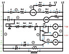
Ladder diagram with identifiers.
Ladder diagrams are also drawn with other helpful identifiers to aid a technician in electrically troubleshooting a system. Each horizontal line on the diagram is identified by a number printed to the left (in green in the example shown) of the diagram.
There may also be a series of numbers printed to the right of one or more of the horizontal lines. In our example, we have colored these numbers red. These numbers represent the line number of the switch or switches controlled by the load in that line. If the number is underlined it identifies the switch as being normally closed; if the number is not underlined the switch is normally open.
In the example shown, line 5 has the numbers 5 and 11 printed to the right of the line. This means that the load (HR) controls a set of contacts in lines 5 and 11. The contact in line 5 is normally open and the contact in line 11 is normally closed.
Many times there are also small numbers printed next to each of the electrical components on the diagram. In our example, we have colored these numbers blue. These smaller numbers represent the manufacturer’s numbers stamped on the actual electrical component. For example, the compressor overload OL2 has the numbers 3 and 4 printed next to it. This means that the wiring shown on the diagram will be physically connected to terminals 3 and 4 on the actual overload. This allows a technician to more easily locate an exact point in the wiring of the system.
Lastly, some diagrams will also have a circled number shown next to a line on the diagram. These circled numbers are used to identify the actual wires used on the system. For example, in our drawing the circled number 3 is connected between the compressor contact C and OL2. The actual wire used on the system between the compressor contact C and OL2 should have the number 3 stamped on it. This can also be a tremendous aid while troubleshooting a system. Technicians can easily translate the wiring shown on the diagram to the actual system wiring.
Unfortunately not all ladder diagrams are drawn using all of these identifiers. But, the more identifiers used by the equipment manufacturers, the easier it is for a technician to electrically troubleshoot the systems.
Publication date: 04/06/2009
Looking for a reprint of this article?
From high-res PDFs to custom plaques, order your copy today!


