The Challenges Of Chiller Compressors
The compressor then increases the pressure and temperature of the refrigerant gas to a point above the ambient air and water temperatures in order for the heat to flow out of the refrigerant into the outdoor air and water. This allows the refrigerant to condense.
In essence, the compressor is a vapor pump.
Reciprocating compressors are the most common compressors used in ice arenas. Recently there has been increased interest in the screw compressor, which takes up less floor space per ton of refrigeration and requires less ongoing maintenance due to a minimum of moving parts.

Problem Prevention
Oil levels should be checked daily on all compressors. If the oil gets low on a system using CFCs, HCFCs, or HFCs, service work should be done quickly. On ammonia systems, oil will eventually log in the chiller, which makes adding oil to the compressor a necessity. The amount of oil added should be recorded to indicate potential problems.Filters should be turned on a daily basis. The temperatures of water jackets should be checked daily and each head physically verified for proper temperature.
Pump failures, plugged filters, closed valves, and mineral buildup can cause stoppages in water flow. All problems should be rectified immediately.
Operating pressures and temperatures should be recorded each shift to warn of any problems. Discharge temperature should not exceed 285 degrees F for ammonia. The suction pressure should not vary much from its normal operating condition.
If the suction pressure is low, it could indicate a brine flow problem, lack of refrigerant, plugged metering device, plugged filters, high oil level in the chiller, or a faulty gauge.
Looking for quick answers on air conditioning, heating and refrigeration topics? Try Ask ACHR NEWS, our new smart AI search tool. Ask ACHR NEWS
If the suction pressure is high, it could indicate an improper metering device setting, high head pressure conditions, broken compressor valves, or a faulty gauge.
Check the compressor seals regularly and monitor the amount of oil dripping in your catch basin. Don't let oil drip onto the floor. Refer to manufacturer recommendations for the acceptable amount of oil that can drip from the seal.
Liquid refrigerant should not be allowed to enter the compressor. Liquid refrigerant cannot be compressed and could destroy a compressor by hydraulic shock if it enters in large volumes. In small volumes, liquid refrigerant will dilute the oil and contribute to bearing failure.
Liquid refrigerant can enter a compressor through the suction line or oil return line due to an overcharged system (critically charged only), extremely high oil level in the chiller (critically charged only), faulty controls on a system with a receiver, or undersized risers causing liquid pickup due to excessive velocities. Liquid might come through the oil return line if the discharge check valves are leaking.
All compressors should have a crankcase heater installed and set 20 degrees higher than the maximum anticipated room temperature.

The Oil Return System
On a typical system using CFCs, HCFCs, or HFCs, oil return usually is not a problem. Oil is miscible (mixes) with those refrigerants and travels through the system with the refrigerant liquid and gas. An oil management system is usually not required in such systems.With ammonia systems, however, additional steps must be taken to return the oil to the compressor. Oil and ammonia are not miscible.
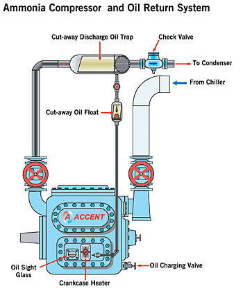
Install an oil separator in the compressor discharge line to separate oil entrained in the discharge gas. The oil drops to the bottom of the separator and runs into the drain line, which has an oil float in it. The float ensures that hot discharge gas does not blow by into the compressor. When the float chamber has oil in it the float will lift, allowing the oil to return to the crankcase.
A check valve placed downstream of the oil separator prevents condensed ammonia from entering the separator when the compressor is off. If condensed ammonia should enter the separator, it would cause the float to lift, allowing liquid refrigerant to enter the compressor.
A crankcase heater should be installed on all compressors to keep the oil temperature 20 degrees above the room temperature. This prevents ammonia from migrating into the compressor during the off cycle. The heater also boils out any small amounts of liquid ammonia that might have reached the compressor crankcase through the suction or oil return line.
A small amount of oil always bypasses the separator and will settle out at the coldest spot in the system, the chiller. Over time the oil will displace the ammonia, reducing the heat transfer surface of the chiller. In extreme cases, a very large quantity of oil will actually displace the ammonia to the point that it will cause liquid ammonia to enter the compressor through the suction line.
In order to prevent a buildup of oil in an ammonia chiller, an oil drain pot is installed. It must be checked on a monthly basis. Always record the amount of oil added or drained from a system as a physical check on consumption and possible oil logging problems.
The Screw Compressor
The rotary screw compressor has been around since the 1930s. However, it has only become popular in the recreational ice industry over the last 10 years.More often than not, it is employed in facilities with two or more sheets of ice. With the popularity of smaller screw compressors, it is becoming feasible to apply them in smaller facilities as well.
Like the reciprocating compressor, the screw compressor is a positive-displacement compressor. Compression is achieved by en-trapping a volume of gas between a pair of rotating "screws" that resemble the auger of a meat grinder. The gas is forced into an ever-decreasing volume until it is released at the discharge port.
To seal the gas between the rotating screws, a large volume of oil is injected. The oil picks up a great deal of the heat of compression and therefore must be cooled by an external source such as water, liquid injection, or thermal siphon oil cooling.
To prevent large quantities of oil from passing through into the remainder of the refrigeration system, install efficient coalescent oil filters on the screw compressor packages.
Screw compressors have a large refrigeration capacity per square foot of floor area. They are easily unloaded to match a given refrigeration capacity.
This is accomplished through the use of a slide valve, which changes the location along the screw where the suction gas enters the compression cycle.
There is a loss of efficiency when the system is unloaded. On a single ice surface, it would be better to operate the compressor at 100 percent and shut it off upon achieving the desired temperature.
As mentioned before, screw compressors have few moving parts and offer a long operating period between overhauls. They are worth considering for an increasing number of applications.
Art Sutherland is a partner with Accent Refrigeration Systems Ltd., Victoria, British Columbia; www.accent-refrigeration.com.
Sidebar: Screw Compressor Maintenance Tips
Sidebar: Recip Compressor Maintenance Tips
Publication date: 04/04/2005
Looking for a reprint of this article?
From high-res PDFs to custom plaques, order your copy today!


