Simulation Helps Reduce Chlorine Concentration In Lab
Workers throughout a wide range of chemical processing industries are becoming more conscious than ever before of discharges that, although they fall within acceptable safety limits, cause annoyance and potential discomfort. The approach of redesigning process equipment in order to eliminate the discharges at the source is the ideal solution in the case where the process is being overhauled for other reasons, but is otherwise often too costly to consider. The more practical approach is usually to retrofit an exhaust system to the existing equipment to remove as much of the contaminants as possible before they are circulated through the plant. This approach, however, also has its challenges.
Facilities management planned to install an exhaust system to eliminate chlorine odor but were uncertain how the exhaust system should be configured to have the greatest impact. It would have been very expensive to install the exhausts in several different locations in order to see which configuration worked best. Thus, management hired a consulting firm to use computational fluid dynamics (CFD) to simulate the performance of the most likely design alternatives. The consultant analyzed four different cases and found which one worked best. The chemical company installed the exhaust system based on these guidelines and discovered that the new system fully solved the problem.
Traditional Approach Involves Cost And Disruption
Exhaust system performance is highly dependent upon a number of variables such as the flow and pressure conditions inside the plant, the distribution of the various sources of contaminants, and the placement and capacity of the exhaust system. But it is impractical to measure the flow and pressure to any significant degree of accuracy, so the best that engineers can do in most cases is make a rough hand calculation or educated guess as to which configuration will work best.The accuracy of hand calculations is reduced by several factors. First, these calculations don't take the geometry of the structure into account. Second, they determine only average chemical concentrations but not the spatial distribution or gradients in the distribution, both of which are important.
The result is that engineers are unable to be certain about the performance of a prospective design until the ventilation system is installed and tested. Usually such a system is installed, the concentration of the contaminants is measured, and the performance of the system is assessed. If the design does not meet the requirements, then it becomes necessary to perform a costly and, at times, disruptive series of experiments, modifying the design and evaluating its performance until the design criteria are satisfied.
Simulating Airflow In Software
CFD can dramatically improve this process by predicting airflow, pressure, and chemical concentrations throughout a region with a high level of accuracy. CFD uses numerical methods to solve the fundamental nonlinear differential equations that describe fluid flow (the Navier-Stokes and allied equations), for predefined geometries, boundary conditions, process flow physics, and chemistry. The result is a wealth of predictions for flow velocity, temperature, density, and chemical concentrations for any region where flow occurs. CFD is a potent, non-intrusive, virtual modeling technique with powerful visualization capabilities. A key advantage of CFD is that engineers can evaluate the performance of a wide range of exhaust system configurations on the computer without the time, expense, and disruption required to make actual changes onsite.Flonomix engineers selected Airpak, a CFD software package from Fluent Inc., Lebanon, N.H. Airpak is specially designed to simplify the process of modeling ventilation systems. It applies state-of-the-art CFD technology to the design and analysis of ventilation systems, which deliver indoor air quality (IAQ), thermal comfort, health and safety, air conditioning, and contamination control. The software is also useful for understanding external flows around buildings, and how external airflow impacts natural ventilation inside buildings. The ability to rapidly create and automatically mesh ventilation system problems (using real rather than compromised geometries) is coupled with a fast, accurate, and well-proven unstructured solver engine. Simulation time is reduced through the use of object-based model building with predefined objects, such as rooms, people, fans, partitions, vents, openings, walls, sources, resistances, ducts, and hoods.

Modeling The Laboratory
On this project, the engineers worked with floor plans provided by the chemical laboratory, direct measurements and observations, and photos taken in the lab. The computational domain covered an area 131 feet long, 24 feet high, including 4 feet under the floor, and 126 feet deep. They created a CFD model that used about 850,000 cells to reproduce the geometry of open space within the plant. The model took about 10 hours to solve on a fast personal computer. An air balancing report was provided by Pro Control that measured air moving in and out of the laboratory at various locations. The boundary conditions were created based on this report.Chlorine sources were located in the sump area, trench area, and on the surface of three tanks. The laboratory itself provided measurements on the volume of chlorine emitted by the various sources in the plant. The values for chlorine were not accurate enough to determine absolute values for chlorine concentration, but were sufficient to meet the objectives of this study by determining the relative performance of various design alternatives. A conventional k-e turbulence model was used.

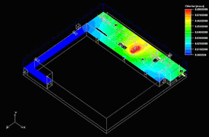
Evaluating Conditions With All Sources On
With this key point established, Flonomix engineers moved on to evaluate the effects of adding the other sources. They positioned exhausts under the covers of the sumps and trenches, the design that was shown to be best from the earlier simulation. Then they added additional 400 cfm exhausts above the three tanks while varying the gap between the top of the tank and the exhaust at 2 feet and 4 feet. The results of these simulations showed that placing the exhausts 2 feet above the tanks provided superior results.
Heejin Park is president of Flonomix Inc., Eden Prarie, Minn. He can be contacted at hjpark@flonomix.com. For more information on the Fluent CFD software, contact: Fluent Inc., 10 Cavendish Court, Centerra Resource Park, Lebanon, NH 03766; 603-643-2600, 603-643-3967 (fax); www.fluent.com.
Publication date: 07/05/2004
Looking for quick answers on air conditioning, heating and refrigeration topics? Try Ask ACHR NEWS, our new smart AI search tool. Ask ACHR NEWS
Looking for a reprint of this article?
From high-res PDFs to custom plaques, order your copy today!


