Understanding a Defrost Board on a Heat Pump
Prevent cold-weather callbacks and diagnose issues faster
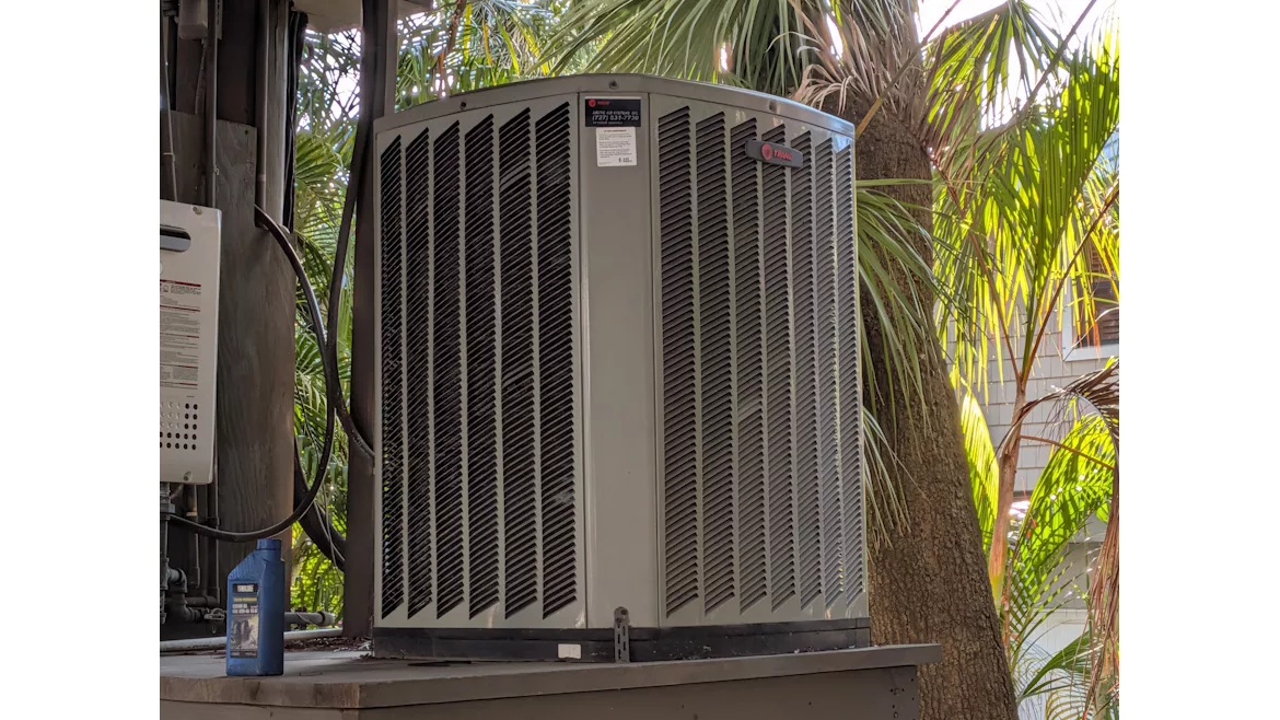
THE CORRECT PROCESS: Objective testing is the best method to prescribe a remedy.
As we head into the colder months, HVACR technicians need to understand the fundamentals of defrost control board operation. While there are many types of defrost control boards on the market, they all function similarly. Let’s break down the basics so you’re prepared to handle this common cold-weather issue.
Understanding the Defrost Control Board
Let’s begin with the thermostat terminals on the defrost control board (see Figure 1.0). This particular board includes the following terminals: R, C, O, Y, and W.
- R supplies a constant 24 volts to the board.
- C is the common terminal.
- O controls the operation of the reversing valve.
- Y controls the compressor contactor.
- W is energized when the heat pump enters defrost mode, activating the emergency (or auxiliary) heat inside the home.
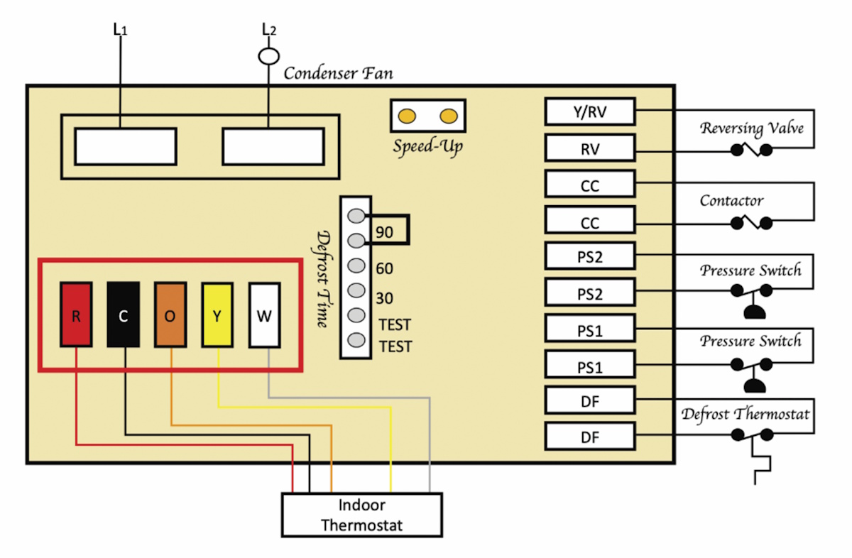
FIGURE 1 (Courtesy of ACCA).
Now, let’s focus on the right side of the board. These will be our terminal designations (see figure 2.0). Starting at the bottom, outlined by the red box, we will begin with the terminals labeled DF. These terminals are the defrost thermostat. The most frequently used method of determining when to initiate a defrost is based on time and temperature. The defrost thermostat senses the outdoor coil temperature.
For example, when the coil temperature is below 30°F ±3°F, the defrost thermostat completes a circuit to the control logic in the defrost board. In the green box of Figure 2.0, this highlights the defrost time. The time counts down the defrost starting time whenever the unit is running in the heat. When the defrost time is reached, the timer will always try to initiate the defrost cycle. Defrost time can be set for various defrost intervals. These are typically 30-, 60-, and 90-minute intervals.
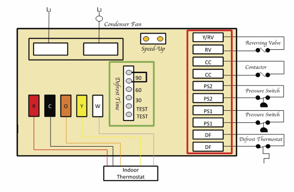
FIGURE 2 (Courtesy of ACCA).
Next, we will move on to PS1, or the low-pressure switch, and PS2, or the high-pressure switch. Keep in mind, some units may have a pressure switch, and some may not. For example, the airflow pressure differential across the outdoor coil initiates the defrost cycle, and the temperature of the liquid leaving the coil terminates it. The defrost cycle is activated when the frost buildup causes enough airflow resistance to close the differential pressure switch.
The CC is the compressor contactor. Some manufacturers may identify it as a control contactor. Regardless of the name, the contactor, when closed, will allow the compressor to operate.
Finally, on this side of the board, we have the RV and Y/RV. These terminals are for the reversing valve. Some heat pumps energize the reversing valve in heating, while others energize the reversing valve in cooling. Regardless of which method is used, the reversing valve must shift from heating to cooling for a defrost cycle.
Looking for quick answers on air conditioning, heating and refrigeration topics? Try Ask ACHR NEWS, our new smart AI search tool. Ask ACHR NEWS
Today, more units energize the reversing valve in cooling than in heating. Therefore, they typically use the O terminal to energize the reversing valve. For these systems, the reversing valve must be energized in defrost.
Next up is the condensing fan relay, outlined by a red box in Figure 3.0. The condenser fan relay on this board controls the condenser fan. When the unit goes into defrost, this relay is not energized. So, the condenser fan does not run while the system is defrosting. From my experience, many technicians forget that this relay must transfer power from line one to line two when operating in air conditioning mode.

FIGURE 3 (Courtesy of ACCA).
Troubleshooting Tips
If you suspect the defrost board is bad, examine the board, and you will see either the word “Test” or “Speed-Up” (see Figure 4.0.) You can use a jumper wire to jump the test pins or jump the speed-up pins. By doing this, it will exponentially speed up the defrost cycle. It also allows you to check the operation of the defrost control board to ensure everything is operating correctly.
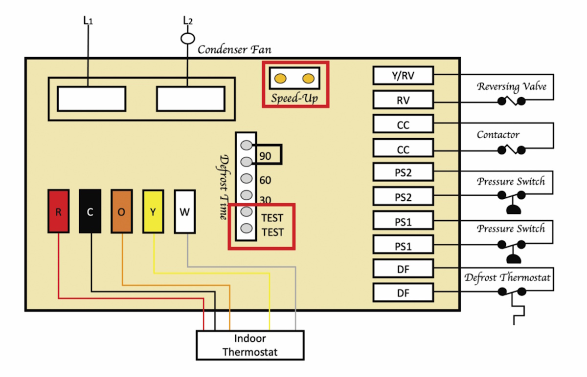
FIGURE 4 (Courtesy of ACCA).
The first step is to ensure the defrost thermostat is cold enough to allow a defrost. If the coil is not frosted, you should disconnect the outdoor fan from the defrost control board and operate the unit in heating mode until the area where the defrost thermostat is located is frosted.
Next, jump the test pins or the speed-up pins on the defrost control board. By doing this, it should send the system into a defrost within a few seconds. Typically, the system will remain in defrost until the defrost thermostat senses that the coil is 50-70°F. Always reference the OEM’s literature for necessary temperatures and ranges. If the system does not go into defrost, you need to trick the board into thinking the coil is cold.
For systems using time-temperature boards that use defrost thermostats, the defrost thermostat connections can be jumped out on the board. For defrost control boards that use thermistors, disconnecting the coil thermistor simulates extremely cold conditions. This is because most thermistors used in these systems have a negative temperature coefficient — meaning their resistance decreases as temperature increases. In other words, high resistance indicates a low temperature.
Defrost thermostats are larger and typically have larger-gauge wires, while thermistors are small with much smaller wires. Figure 5.0 shows a defrost thermostat, and Figure 6.0 shows a defrost thermistor.

FIGURE 5 (Courtesy of ACCA).

FIGURE 6 (Courtesy of ACCA).
Why Does This Matter?
The defrost function of a heat pump is essential for maintaining its proper operation during the heating mode. The defrost function must be activated early enough to eliminate ice formation but not often enough to reduce efficiency. Understanding the defrost function can help technicians identify issues early that may lead to significant breakdowns, leaving your clients without heat.
Additionally, troubleshooting the defrost control board can help reduce callbacks by accurately diagnosing these types of issues. Accurate diagnostics through proper testing can help clients decide to repair or replace their system based on the severity of the heat pump's problems.
Finally, objective testing is the best method to prescribe a remedy. Remember, a prescription without a diagnosis is malpractice. Don’t guess when you can test!
Looking for a reprint of this article?
From high-res PDFs to custom plaques, order your copy today!