Air-Cooled Condenser Coil Leaks Problem
Some years ago it was common for air-cooled condensers to develop leaks, resulting in unpredictable shorter service life. By studying the causes of the problem, it’s possible to come up with solutions. It became obvious that vibration was the major culprit, and thermal expansion/contraction creates some specific problems where the hot gas first enters the coil. To discuss this, we’ll look first at leaks at the tube sheets caused by vibration - by far the major culprit - then leaks at the discharge header, a result of either vibration or thermal expansion/contraction or both.
 1. The most common type of leak occurs on the bottom of the tube where it passes through the tube sheet. These do not occur when the tube is expanded to a tight fit but when there is a clearance between the expanded tube and its matching through-hole in the tube sheet. Studies show that it does not matter whether the tube sheet is steel or aluminum, or the holes formed with collars, clean punched, or even fitted with bushings. With vertical vibration, the tubes bounce on the tube sheet holes and start to work harder at the point of contact. When the vibration is strong enough and lasts long enough, stress cracks develop and become leaks.
But there is very little wearing on the tubes. These most often happen on the bottom row of a coil. This bottom row carries the greatest weight (the refrigerant is now liquid). This bottom row is also where the flexing of the corrugated fins allows the tubes to make greatest contact with the tube sheet during bouncing. These failures happen at the intermediate tube sheets since these carry twice the weight of end sheets.
2. A second cause of leaks is due to flexing of the coil bundle when vibration is present. The possibility of this happening is magnified by having fewer rows of tubes and/or a wide span between supports. Engineering figures show that a 25 percent reduction in rows (four rows to three rows) results in about a 60 percent increase in flexing. Similarly, a 15 percent increase in span (from 48 to 55 inches, for example) results in about a 50 percent increase in flexing. This type of leak shows up as a fatigue crack across the top of the tube at the support point and can eventually result in the tube totally breaking off at the tube sheet.
1. Thermal expansion/contraction of the tubes in contact with the tube sheet.
2. The discharge header itself expands/contracts, bending the tubes and creating fatigue.
3. Improper support of field piping amplifies vibration.
Leaks can occur if the tube sheet makes contact with the tubes that are attached to the discharge header. Thermal expansion/contraction of the tubes causes wear. Most manufacturers have solved this problem by having clearance holes in the tube sheet at these locations (essentially the top row).
Leaks can be caused by the thermal expansion/contraction of the discharge header itself. Because the expansion coefficient is linear, a long header expands more than a short header. The outermost tubes connected to the header will therefore bend the most. Headers over 4 feet long can cause fatiguing of the outermost tubes. In an actual application field manifolding should be configured so that some of the expansion/contraction can be absorbed at the manifolds.
Leaks also result from improper support of field piping connected to either the discharge or liquid headers. Piping with multiple bends very quickly amplifies compressor pulsations or any other vibrations. The resulting stress is concentrated at the core tubes that tie into the header, right at the point where these tubes pass into the core bundle. Small circuits with only one, two, or three tubes into the header are particularly susceptible to leaks from this cause.
• Over-the-road shipping vibration;
• Compressor pulsation;
• Motor bearing failure;
• Bent, broken, or dirty fan blade;
• Dirty condenser;
• Broken motor mounts;
• Loose bolts;
• Fan cycling; and
• Blocked or frozen dampers.
Publication date: 06/06/2011
VIBRATION CAUSED LEAKS AT TUBE SHEETS
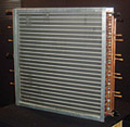
The most frequently reported leaks have been at the intermediate tube sheets. While all leaks are problems, these are particularly troublesome since they are almost impossible to repair. As you’ll see in the specific examples discussed later, these are all caused by vibration. If they were caused by thermal expansion/contraction, they would appear in the top row since that’s where the greatest changes in temperature occur (the hot discharge gases enter the coil here and the majority of all heat loss, or exchange, occurs in the top row). However, almost totally, leaks are reported in the bottom row of tubes where the temperature is the most stable. Let’s look at the two types of leaks in more detail.Condenser coil with special feeds and return bend pattern.
But there is very little wearing on the tubes. These most often happen on the bottom row of a coil. This bottom row carries the greatest weight (the refrigerant is now liquid). This bottom row is also where the flexing of the corrugated fins allows the tubes to make greatest contact with the tube sheet during bouncing. These failures happen at the intermediate tube sheets since these carry twice the weight of end sheets.
2. A second cause of leaks is due to flexing of the coil bundle when vibration is present. The possibility of this happening is magnified by having fewer rows of tubes and/or a wide span between supports. Engineering figures show that a 25 percent reduction in rows (four rows to three rows) results in about a 60 percent increase in flexing. Similarly, a 15 percent increase in span (from 48 to 55 inches, for example) results in about a 50 percent increase in flexing. This type of leak shows up as a fatigue crack across the top of the tube at the support point and can eventually result in the tube totally breaking off at the tube sheet.
Multiple circuits in typical condenser coil.
LEAKS IN THE DISCHARGE HEADER
There are generally three causes of leaks in the area of the discharge header:1. Thermal expansion/contraction of the tubes in contact with the tube sheet.
2. The discharge header itself expands/contracts, bending the tubes and creating fatigue.
3. Improper support of field piping amplifies vibration.
Leaks can occur if the tube sheet makes contact with the tubes that are attached to the discharge header. Thermal expansion/contraction of the tubes causes wear. Most manufacturers have solved this problem by having clearance holes in the tube sheet at these locations (essentially the top row).
Leaks can be caused by the thermal expansion/contraction of the discharge header itself. Because the expansion coefficient is linear, a long header expands more than a short header. The outermost tubes connected to the header will therefore bend the most. Headers over 4 feet long can cause fatiguing of the outermost tubes. In an actual application field manifolding should be configured so that some of the expansion/contraction can be absorbed at the manifolds.
Leaks also result from improper support of field piping connected to either the discharge or liquid headers. Piping with multiple bends very quickly amplifies compressor pulsations or any other vibrations. The resulting stress is concentrated at the core tubes that tie into the header, right at the point where these tubes pass into the core bundle. Small circuits with only one, two, or three tubes into the header are particularly susceptible to leaks from this cause.
CAUSES OF VIBRATION
As you can see, most leaks result from vibration. There are many sources of vibration, most out of the control of the condenser manufacturer. Examples include:• Over-the-road shipping vibration;
• Compressor pulsation;
• Motor bearing failure;
• Bent, broken, or dirty fan blade;
• Dirty condenser;
• Broken motor mounts;
• Loose bolts;
• Fan cycling; and
• Blocked or frozen dampers.
Publication date: 06/06/2011
Looking for a reprint of this article?
From high-res PDFs to custom plaques, order your copy today!


