The Critical Nature Of Cap Tubes
Cap tubes are mainly used because of their simplicity and low cost. Also, systems employing capillary tubes as metering devices do not require receivers, lowering their cost still further.
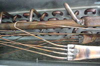
Cap tube systems are found mainly in domestic and small commercial applications that experience relatively constant evaporator heat loads, have relatively small refrigerant flow rates, and employ hermetic compressors. Many large commercial rooftop air conditioning systems also use capillary tubes as their metering devices. (See Figure 1.)
A capillary tube is nothing but a long, fixed-length tube with a very small diameter. The diameter can range from 0.024 to 0.120 inches.
How Flashing Occurs
The cap tube is installed between the condenser and the evaporator. It meters the refrigerant moving from the condenser to the evaporator. Because of the tube's long length and small diameter, there is an associated large friction loss as refrigerant flows through the tube.In fact, as subcooled liquid refrigerant travels through the tube, it may experience pressure drops, which may bring it lower than the saturation pressure for its temperature. The flashing that results is caused by the expansion of the liquid as it experiences this pressure drop.
The amount (if any) of liquid that flashes depends on the amount of liquid subcooling coming from the condenser, liquid line, and in the cap tube itself. If liquid flashing does occur, it is desirable to keep the flashing as close to the evaporator as possible to ensure better system performance.
Capillary tubes are usually twisted around, run inside, or soldered to the suction lines to add to the subcooling effects, to help prevent liquid flashing in the capillary tube.
Because the capillary tube restricts and meters the flow of liquid to the evaporator, it helps maintain the needed pressure difference for proper system operation.
Looking for quick answers on air conditioning, heating and refrigeration topics? Try Ask ACHR NEWS, our new smart AI search tool. Ask ACHR NEWS
Cap Tubes vs. TEVs
Unlike the thermostatic expansion valve metering device, the capillary tube has no moving parts and does not control evaporator superheat in all evaporator heat loading conditions.Even with no moving parts, the capillary tube will vary flow rate as system pressures change in the evaporator, in the condenser, or both. In fact, it can only reach its best efficiency at one set of high- and low-side pressures.
This is because the capillary tube works off of the pressure difference between the high and low sides of the refrigeration system. As the pressure difference between the high and low sides of the system becomes greater, the flow rate of refrigerant increases.
The capillary tube will operate satisfactorily over quite a large range of pressure differences, but not very efficiently.
Because the capillary tube, evaporator, compressor, and condenser operate in series, the flow rate of the cap tube must be equal to the compressor's pumping rate.
It's critical that the designed length and diameter of the capillary tube are appropriate to the system's designed evaporator and condensing pressures, and must be equal to the compressor's pumping capacity at these same design conditions.
Resistance
Too many turns in the capillary tube will affect the resistance it has to refrigerant flow and, in turn, will affect the system's balance.If the cap tube's resistance is too great because the tube is too long, we say that a partial restriction exists. Also, if the diameter is too small or there are too many turns as it is coiled, the capacity of the tube will be less than that of the compressor.
Cap tube resistance causes the evaporator to be starved, causing low suction pressure and high superheats. At the same time, subcooled liquid will back up into the condenser, causing higher head pressure - remember, there is no receiver to hold the backed-up refrigerant.
The higher head pressure and lower evaporator pressure will cause a greater pressure difference across the capillary tube, causing the refrigerant flow rate to increase. At the same time, the compressor capacity will decrease because of higher compression ratios and lower volumetric efficiencies.
This will cause the system to again establish a capacity balance between compressor capacity and cap tube capacity. However, this balance will be at higher head pressures and lower evaporating pressures, resulting in operating inefficiencies.
If the resistance of the capillary tube is less than called for because it's too short or its diameter is too large, the refrigerant flow through it will be greater than the pumping capacity of the compressor.
This will cause high evaporator pressures, low superheats, and possible compressor flooding due to evaporator overfeeding. Subcooling will drop in the condenser, causing low head pressures and even a loss of liquid seal at the condenser's bottom.
This low head pressure and higher-than-normal evaporator pressures will decrease the compression ratio of the compressor, causing high volumetric efficiencies. This will increase the pumping rate of the compressor and a balance will again be reached if the compressor can keep up with the high refrigerant flow in the evaporator. Usually flooding occurs and the compressor fails to keep up.
To avoid these problems, size the capillary tube properly by calling the manufacturer or using the manufacturer's sizing charts and/or tables. Cap tube lengths usually fall between 5 to 16 feet based on manufacturer sizing charts.
Anything longer than 16 feet is not responsive enough to changes in system head pressures as applied to refrigerant flow rates. Capillary tubes shorter than 5 feet will cause large reductions in refrigerant flow rates. When cap tubes are already less than 5 feet long, even small decreases in length will have a drastic effect on refrigerant flow rates.
Capillary tube systems have an exact or critical charge of refrigerant. Too much or too little refrigerant will cause a severe system imbalance and could seriously damage compressors due to slugging, flooding, or overheating.
High Heat Loads
Under high evaporator heat loading, cap tube systems normally run high evaporator superheats; 40 degrees to 50 degrees F of evaporator superheat is not uncommon at these high evaporator loads. The refrigerant in the evaporator will vaporize rapidly, driving the 100 percent saturated vapor point back up in the evaporator, giving the system a high superheat reading.The capillary tube simply does not have a feedback mechanism like a TEV remote bulb to tell the metering device that it is running high superheat. This can cause the system to run inefficiently at higher loads, and is perhaps one of the main disadvantages of a cap tube system.
Many technicians will have the urge to add more refrigerant to the system at these high evaporator heat loads because of the high superheat readings. Adding refrigerant at this point will only overcharge the system. Before adding refrigerant, check the evaporator superheat reading at the low evaporator loading just before the compressor cycles off. See if it is normal or not.
If you are unsure, recover the refrigerant, evacuate the system, and add the specified nameplate critical charge of refrigerant.
Low Heat Loads
Once the high heat load on the evaporator drops off and the system is under a low load, the 100 percent saturated vapor point in the evaporator will climb down the last passes of the evaporator. This is caused by the refrigerant's decreased rate of vaporization in the evaporator due to the low heat loading.The system will now have a normal evaporator superheat of about 10 degrees to 12 degrees. These normal readings will only occur with low heat loads on the evaporator, just before the compressor cycles off.
If a cap tube system is overcharged, it will back up the excess liquid into the condenser, causing high head pressures. The pressure difference between the low and high sides of the system will now increase, increasing the refrigerant flow rate to the evaporator and overfeeding the evaporator, causing low superheats. It may even flood or slug the compressor.
Again, this is why a capillary tube system must be charged with a specified amount of refrigerant.
Capillary tube systems do not stop the flow of refrigerant after the compressor is shut off by the cycling control. In fact, refrigerant will continue to flow from the condenser to the evaporator until high and low pressures equalize. Most of the subcooled liquid in the condenser will flow through the capillary tube to the evaporator during the off cycle.
This is another reason why the cap tube system is critically charged. Too much liquid in the evaporator during the off cycle can cause compressor damage at startup.
The refrigerant charge should be exact enough to satisfy the requirements of the evaporator and maintain a subcooled liquid seal at the condenser's bottom and capillary tube entrance. If any excess refrigerant is added past the critical charge, subcooling liquid will back up in the condenser, again causing high head pressures and operating inefficiencies.
It is important that large commercial capillary tube systems have accumulators at their evaporator outlets to catch any liquid that may escape vaporization in the evaporator during startups. Liquid coming from the evaporator enters the bottom to the accumulator and the vapors are drawn from the top into the compressor.
Because of this pressure equalization during the off cycles, cap tube systems can employ low-starting-torque motors. These motors usually use current starting relays, sometimes without starting capacitors.
John Tomczyk is a professor of HVACR at Ferris State University, Big Rapids, Mich., and the author of Troubleshooting and Servicing Modern Air Conditioning & Refrigeration Systems, published by ESCO Press. To order, call 800-726-9696. Tomczyk can be reached by e-mail at tomczykj@tucker-usa.com.
Publication date: 02/07/2005
Looking for a reprint of this article?
From high-res PDFs to custom plaques, order your copy today!


