Pressurization Of Closed Hydronic Systems
Closed systems must be pressurized to satisfy three requirements:
1. The pressure at the fill point must be high enough to push the fluid to the top of the system. This is normally only a concern when the fill point is in the basement, but you can understand why there would be problems if there were literally no fluid in the top part of the system.
2. Maintain enough pressure to satisfy the NPSH requirements of the circulation pumps, and prevent cavitation in control valves. For systems operating below about 230 degrees F, centrifugal pumps will require a minimum of 4 psig at the pump suction. Control valves, particularly in heating systems, must be evaluated to determine the pressure required at the outlet to prevent cavitation.
3. Keep all points in the system above atmospheric pressure to prevent the ingestion of air, and to allow air-venting devices to work properly. Good air removal is crucial to the proper operation of any closed system.
It is generally accepted that if a minimum pressure of 4-5 psig is maintained at the top of a closed hydronic system, all of the above requirements will be met with the possible exception of cavitation in hot water control valves. For systems with the fill point located at the top, the standard cold fill pressure setting of 12 psig on commonly available fill devices is more than adequate. Quite often, the static pressure is increased in the mistaken belief that it will improve performance; it doesn't. Pumps do not pump more and boilers do not heat more just because the system static pressure is higher. Increased system pressure may help to solve some air problems, but air binding is really a balance problem, and should be approached from that perspective.

For systems with the fill point at the bottom of the system, it may be necessary to calculate the required cold fill pressure. To do this, determine the height from the gauge used to measure system pressure, to the top of the system in feet. Note that it is the height from the gauge, and not the fill point itself unless they are at the same point. Divide this figure by 2.3 to get psi, and add 4-5 psi for the required minimum pressure at the top.
For example, a system with a static height above the gauge of 40 feet will require a cold fill of (40/2.3) = 17.4 + 5 = 22 psig (see Figure 1). The fill device must then be adjusted to get that pressure on the gauge when the system is cold. If using a gauge at some point in the system where the pressure is affected by running the circulator, ensure that the circulator is off before checking the system pressure. Or, better yet, install a gauge at the fill point. Using the above calculation in reverse, the standard factory setting on fill devices of 12 psig would be adequate for a system with a static height of about 18 feet.
If the required cold fill pressure is higher than 12 psig, there is an important step that must be taken if a pre-charged expansion tank is being used. The air charge in the tank must be adjusted to match the cold fill pressure before the tank is connected to the system. If this is not done, the higher water fill pressure will overcome the standard 12-psig air charge in the tank and partially fill it with fluid. When the system heats up, there may not be enough room in the expansion tank to accept the fluid expansion, and the relief valves will open. Adjusting the air charge in a pre-charged tank should always be done with an oil-less compressor or oil-free air.
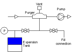
The fill device should always be connected at the same point as the expansion tank and the air separator. This is the "point of no pressure change," and the stable pressure at this point will prevent the fill device from being affected by operation of the pump(s). These components should all be located on the inlet side of the circulating pump (see Figure 2).
For heating systems, the static pressure will increase as the system is heated and the fluid expands. This is normal, and as long as this increase in pressure is kept within the limit of the relief valve, it will not have any impact on performance. Relief valves should not open under any normal operating circumstance; if they do, there is a problem. Find it and correct it.
Once a system is filled and vented, there are three reasons why it can lose pressure:
It is necessary, therefore, to be able to add fluid to the system to maintain the required minimum pressure and keep the system operating satisfactorily. The conventional way of doing this has been to connect a domestic water line to the system through a pressure regulating valve (PRV) set for the required cold fill pressure. In recent years, plumbing codes have added a requirement for backflow prevention on these connections. It is also common to see a bypass piped to allow manual filling of the system. A typical schematic is shown in Figure 3.

There are drawbacks to system pressurization using potable water. Aside from the requirement for backflow prevention and the potential for cross-connection, it is not a good idea to feed raw water into a closed system, particularly if it contains an anti-freeze solution. In fact, the manufacturers of the PRV's used for this purpose recommend that the connection be valved off to prevent unmonitored feeding of raw water, which can result in corrosion, boiler shock, or even flooding. In some jurisdictions, it is a code requirement that these connections be valved off even if they have backflow prevention. In that case, keeping pressure up in the system becomes a manual operation.
The other alternative is to use a packaged hydronic system feeder. These units store a compatible fluid, either pretreated water or an antifreeze solution, in a reservoir and automatically maintain the required system cold fill pressure with no direct connection to a potable water supply. Fluid stored in a feeder tank at atmospheric pressure and room temperature will have much less entrained air than potable water, and monitoring the fluid level in the reservoir will provide an indication of the system make-up rate and give early warning if any leaks develop. Feeders are also easy to alarm if so desired, and they make it a snap to replace fluid drained for service.
System pressurization is a simple concept that is often misunderstood and overlooked as the source of problems in closed systems. As with most other aspects of hydronics, pay attention to the basics and you will have more success.
Reprinted with permission from Radiant Panel Report, a newsletter of the Radiant Panel Association, July 2005. Jerry Boulanger is with Axiom Industries Ltd., Saskatoon, Saskatchewan, Canada. For more information, phone 306-352-0656, fax 306-352-0657, e-mail jboulanger@axiomind.com, or visit www.axiomind.com.
Publication date: 09/19/2005
Looking for quick answers on air conditioning, heating and refrigeration topics? Try Ask ACHR NEWS, our new smart AI search tool. Ask ACHR NEWS
Looking for a reprint of this article?
From high-res PDFs to custom plaques, order your copy today!


