Using The P-T Card As A Service Tool
In spite of the widespread availability and apparent reference to the pressure-temperature relationship, the number of service technicians who use the P-T chart properly in diagnosing service problems is very few.
The purpose of this article is to not only demonstrate the proper use of the pressure-temperature relationship, but to also illustrate how it can be used to thoroughly analyze a refrigeration or air conditioning system.
Refrigerant In Three Forms
Before getting into the proper use of the P-T card, let's review briefly the refrigeration system and examine exactly how the pressure-temperature relationship can be applied.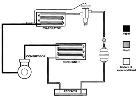
1. All liquid
2. All vapor
3. A mixture of liquid and vapor
Figure 1 illustrates the form in which refrigerant is found at various points in a normal operating refrigeration system.
Notice that the high side contains refrigerant in all of the three conditions listed above. The discharge line contains all vapor. The condenser where the vapor condenses into a liquid contains a mixture of liquid and vapor. The line between the condenser and the receiver usually contains all liquid although it would not be abnormal for this line to also have some vapor mixed with the liquid. Since the receiver has a liquid level at some point, it must be thought of as having a mixture of liquid and vapor. The liquid line leading from the receiver to the thermostatic expansion valve should contain all liquid. A sight glass or liquid indicator is frequently installed in the liquid line to assist in determining if the liquid refrigerant is completely vapor-free.
The low side of the system will usually contain refrigerant in only two of the three forms that were listed previously. That is, the low side will contain all vapor in the suction line and a mixture of liquid and vapor from the outlet of the thermostatic expansion valve to nearly the outlet of the evaporator.
When P-T Relationship Holds True, Refrigerant Is ‘Saturated'
The important thing to remember is that the pressure-temperature relationship as shown by a P-T card is only valid when there is a mixture of refrigerant liquid and vapor.Therefore, there are only three places in the normally operating refrigeration system where the P-T relationship can be guaranteed with certainty. That is the evaporator, the condenser, and the receiver - places where a mixture of refrigerant liquid and vapor are known to exist. When refrigerant liquid and vapor exist together, the condition is known as "saturated."
Looking for quick answers on air conditioning, heating and refrigeration topics? Try Ask ACHR NEWS, our new smart AI search tool. Ask ACHR NEWS
This means that if we are able to determine the pressure at any of these points, we can easily determine the temperature by merely finding the pressure on a P-T card and reading the corresponding temperature. Conversely, if we can accurately measure the temperature at these three locations, we can also determine the pressure from the P-T relationship by finding the pressure corresponding to the temperature that we have measured.
When P-T Relationship Is Not True, Superheat Or Subcooling Is Indicated
At the points in the system where only vapor is present, the actual temperature will be above the temperature that is indicated by the P-T relationship for the pressure we are measuring. The temperature of the vapor can be the same as the pressure-temperature relationship, but in actual practice, it is always above. In this case, the difference between the measured temperature and the temperature corresponding to the pressure that exists at the point in question is a measure of superheat.Where it is known that all liquid is present such as in the liquid line, the measured temperature will be somewhere below the temperature corresponding to the pressure. In this case, the difference between the measured temperature and the temperature corresponding to the P-T relationship is a measure of liquid subcooling. Again, it is possible to find that the actual measured temperature is equivalent to the P-T relationship, in which case the amount of subcooling would be indicated as zero.
Analyzing Actual System For Saturated, Subcooled, Or Superheated Refrigerant
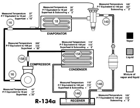
Figure 2 shows some actual pressure-temperature measurements throughout a normally operating system using Refrigerant 134a, which may give a better insight into the condition of the refrigerant at the various points. The measured temperature at the evaporator inlet is 20 degrees F. A gauge installed at this point indicates a pressure of 18 psi; 18 psi on the P-T card indicates a temperature of 20 degrees F - the same as was measured. This is what we should expect since, when refrigerant liquid and vapor are present together, the P-T relationship will hold true.A gauge installed in the suction line measures 16 psi. If there were a mixture of liquid and vapor at this point, the measured temperature would be the same as the P-T relationship or 17 degrees F. However, our actual measured temperature in this case is 27 degrees F. The amount of superheat in the vapor, therefore, at this point is the difference between the measured temperature of 27 degrees F and the indicated temperature (according to the P-T chart) of 17 degrees F. The superheat therefore is 10 degrees F.
If we also measure 16 psi at the compressor inlet with the measured temperature of 47 degrees F, our superheat in this case would be 30 degrees F, calculated by subtracting the temperature equivalent to 16 psi (17 degrees F) from the measured temperature of 47 degrees F.
Let's now examine the gauge we have installed midway in the condenser which reads 158 psi. According to the P-T relationship, the temperature will be 115 degrees F and this is the temperature that we would be able to measure if we placed a thermocouple in the refrigerant at this point, where it is changing from a vapor to a liquid. In other words, there is no difference between the measured temperature and the indicated temperature using the P-T card. It might also be said that the superheat is zero and the subcooling is zero. This condition is also referred to as "saturation."
In our example we also measure 158 psi at a discharge line of the compressor. The measured temperature here is 200 degrees F. Calculating the superheat in the same way as it was done on the suction line, (difference between measured temperature and temperature corresponding to the P-T relationship), it is determined that the superheat is 85 degrees F.
When a system employs the use of a liquid receiver, there can be no subcooling at the surface of the liquid in the receiver. The reason for this is that when liquid refrigerant and vapor exist together, they must obey the P-T relationship or the refrigerant must be saturated. In our example the measured pressure in the receiver is 146 psi; the refrigerant in the receiver must therefore be at 110 degrees F.
Once a solid column of liquid is formed, subcooling of the refrigerant can take place by lowering its temperature with the use of liquid-suction heat exchangers, subcoolers, or from lower ambient temperatures surrounding the line.
Subcooling is a lowering of a temperature below the P-T relationship. In our illustration in Figure 2, subcooling of 5 degrees F and 2 degrees F has been determined as illustrated at two points.
Of course, it is important to maintain some liquid subcooling in the liquid line to prevent flash gas from forming in the liquid line and entering the thermostatic expansion valve.
With the use of a P-T card, we should be able to determine the condition of the refrigerant at any point in the system by measuring both the pressure and the temperature and observing the following rules:
A. Liquid and vapor are present together when the measured temperature corresponds to the P-T relationship. (It is theoretically possible to have "saturated liquid" or "saturated vapor" under these conditions, but practically speaking in an operating system, it should be assumed that some liquid and some vapor are present under these conditions.)
B. Superheated vapor is present when the measured temperature is above the temperature corresponding to the P-T relationship. The amount of superheat is indicated by the difference.
C. Subcooled liquid is present when the measured temperature is below the P-T relationship. The amount of subcooling is represented by the difference.
Practical Limitation To Gauge Locations
In our illustration we have located gauges at points in the system where it is not always feasible to do so on an actual installation. Because of this, we must oftentimes make deductions and assumptions when dealing with an actual system.As an example, we would normally assume that the 158 psi read on the gauge installed at the compressor discharge line is also the pressure that exists in the condenser. That is, we assume that there is no pressure loss of any consequence between the compressor discharge and the condenser. With this reasoning, we arrive at a condensing temperature of 115 degrees F. If an undersized discharge line or other restrictions are suspected, we cannot make this assumption and other pressure taps may be necessary to locate the troublesome area.
It is also common practice to assume that the pressure measured at the suction service valve of the compressor is the same pressure that exists at the outlet of the evaporator at the expansion valve bulb location. This is particularly true on close-coupled systems where it has been determined that the suction line is of the proper size. By making this assumption, we can determine the expansion valve superheat without installing an additional pressure tap at the bulb location. However, to eliminate any doubt as to the amount of suction line pressure drop and to be absolutely precise in measuring superheat, a gauge must be installed in the suction line at the bulb location.
Care must be taken to make a reasonable allowance for pressure drops within the system. Excessive pressure drops can be detected by applying the principles of the P-T relationship. As an example, in Figure 2, with gauges installed only at the suction and discharge of the compressor and reading as indicated, a significant pressure drop through the evaporator would be indicated by a high temperature of, say, 50 degrees F measured at the evaporator inlet which would correspond to a pressure at that point of approximately 45 psi for a pressure drop of 29 psi from the
evaporator inlet to the compressor inlet (45 minus 16). While this would be considered excessive on a single-circuit evaporator, it should be remembered that, on multi-circuit evaporators using a refrigerant distributor, a pressure drop through the distributor on Refrigerant 134a may be in the vicinity of 25 psi. This means that with the use of a refrigerant distributor, a measured temperature between the outlet of the thermostatic expansion valve and the inlet of the distributor of approximately 50 degrees F would not be abnormal in the system illustrated in Figure 2.
Checking On Non-Condensables
The proper use of the P-T relationship can be helpful in discovering the presence of air or other non-condensable gases in the system. This would be revealed by the measured temperature in the condenser or the leaving temperature of the cooling medium being much lower than that indicated by the P-T relationship.Reprinted with permission from Sporlan Valve Company, Form 10-135. For more information, contact Sporlan at 206 Lange Drive, Washington, MO 63090; 636-239-1111; 636-239-9130 (fax); www.sporlan.com.
Publication date: 11/29/2004
Looking for a reprint of this article?
From high-res PDFs to custom plaques, order your copy today!


