Anatomy of a 3-Wire Zone Valve

A GLIMPSE INSIDE: Inside of a power-open-power-close hydronic zone valve, there is a motor that needs to receive separate 24V signals to open and to close the valve. (Courtesy of Lianna Schwalenberg)
In hydronic heating, to control where heated water goes to various sections of a building, the system might rely on two or more zone valves. A zone valve opens or closes based on demand from a thermostat. When the valve is fully open, it makes an “end” switch which tells the main circulator and/or the burners to turn on.
Service technicians will run into many different types of zone valves just in one heating season. I will share a troubleshooting encounter I had with a specific style of 3-wire zone valves known colloquially as a “power-to-open, power-to-close” valve. When I went to this service call—which was a zoned apartment building, two stories, three zones—the zone valve, which was a White Rodgers Type 1311, was spinning non-stop. In effect, it caused poor water flow and not much heating of the space.
I did what every young technician does with little knowledge or patience, I replaced the valve in its entirety—body, head, stem, and guts. But the valve still spun continuously. Only after sitting down, reading the installation instructions, and asking for help did I finally figure out what I needed to do. I took the valve apart to explain it to myself, and now my readers don’t have to do it in the field or under pressure.
Principle of Operation
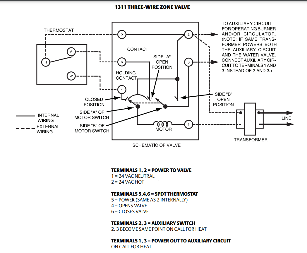
The operational concept of the power-open, power-close valve is in the name: the valve has some kind of motor or mechanism that needs to be told to open on a call for heat and to close when the space is satisfied. Hence, the need for three wires to the thermostat: open, close, and common. There are several manufacturers who make this type of zone valve, including Taco, Honeywell, and White Rodgers.
Specifically with White Rodgers, their 1300 series valves feature a barrel-type valve stem which is spun using a 24V motor. With this design, the valve changes from open to close every 90° turn. This means the valve spins one full revolution after it is told to open twice and close twice. In this regard, it might be more apt to say this is a “power to turn, power to turn again” valve. The valve does not necessarily know whether it is open or closed — only that it is turning or not turning. For convenience, these valves have a disk labeled with “OPEN” and “CLOSED” to indicate what position the valve is in.
While White Rodgers 1311 is by definition a 3-wire valve, technicians will find more than three wires going to this valve which has, in fact, six terminals. The multiple terminals and their designations are described in Figure 1 and in Table 1.
Click graphic to enlarge
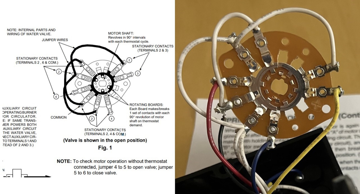
FIGURE 1: The motor knows when to stop spinning when it breaks the “holding contact” which ensures the motor is continuously energized until it spins 90°. (Courtesy of Lianna Schwalenberg)
The motor knows when to stop spinning when it breaks what the manufacturer refers to as the “holding contact.” The holding contact ensures the motor is continuously energized until the motor makes it past the 90° position, which takes about 45 seconds.
Looking for quick answers on air conditioning, heating and refrigeration topics? Try Ask ACHR NEWS, our new smart AI search tool. Ask ACHR NEWS
To mechanically understand what is happening inside the valve, the motor not only spins the barrel, but it also spins a metal collar which makes and breaks sets of stationary switches as it spins. This metal collar is best illustrated as the shaded area in Figure 2. It can be observed that there are three jumped terminals labeled “2” which are hot 24V from the transformer. There are also two jumped terminals labeled “common” which are common wires for the motor. Breaking the “holding contacts” happens when a full 90° turn causes a break between hot and common for the motor.
Click graphic to enlarge
FIGURE 2: Pictured here in the open potion, the valve motor rotates a metal collar, which makes and breaks sets of stationary contacts as it spins. (Courtesy of Lianna Schwalenberg)
When the motor stops spinning, it makes a connection between 4 and common or 6 and common. In essence, the valve sits here and waits for the thermostat to close and send power to cause the valve to spin again. As shown, terminals 2 and 3 are only shorted when the shaft spins 180° – thus, the burners and/or circulator can only be energized when the valve is open.
Order of Operations
The thermostat is calling for heat. The valve is open, and auxiliary contacts are powered to fire the boiler. The valve is not spinning, and hot water is allowed to pass through. Next, the thermostat satisfies, which closes the circuit between 5 and 6 which sends power to the motor to start spinning counterclockwise shaft-end (clockwise viewing the contacts). The motor continuously receives power between terminal 2 “holding” with common. The motor stops spinning when the holding contacts break after 90°, see Figure 3. The valve is closed. The auxiliary contacts are broken; therefore, the burners will not have a closed path at this valve. Because multiple zone valves are wired parallel, the burners may stay on if other valves are calling for heat.
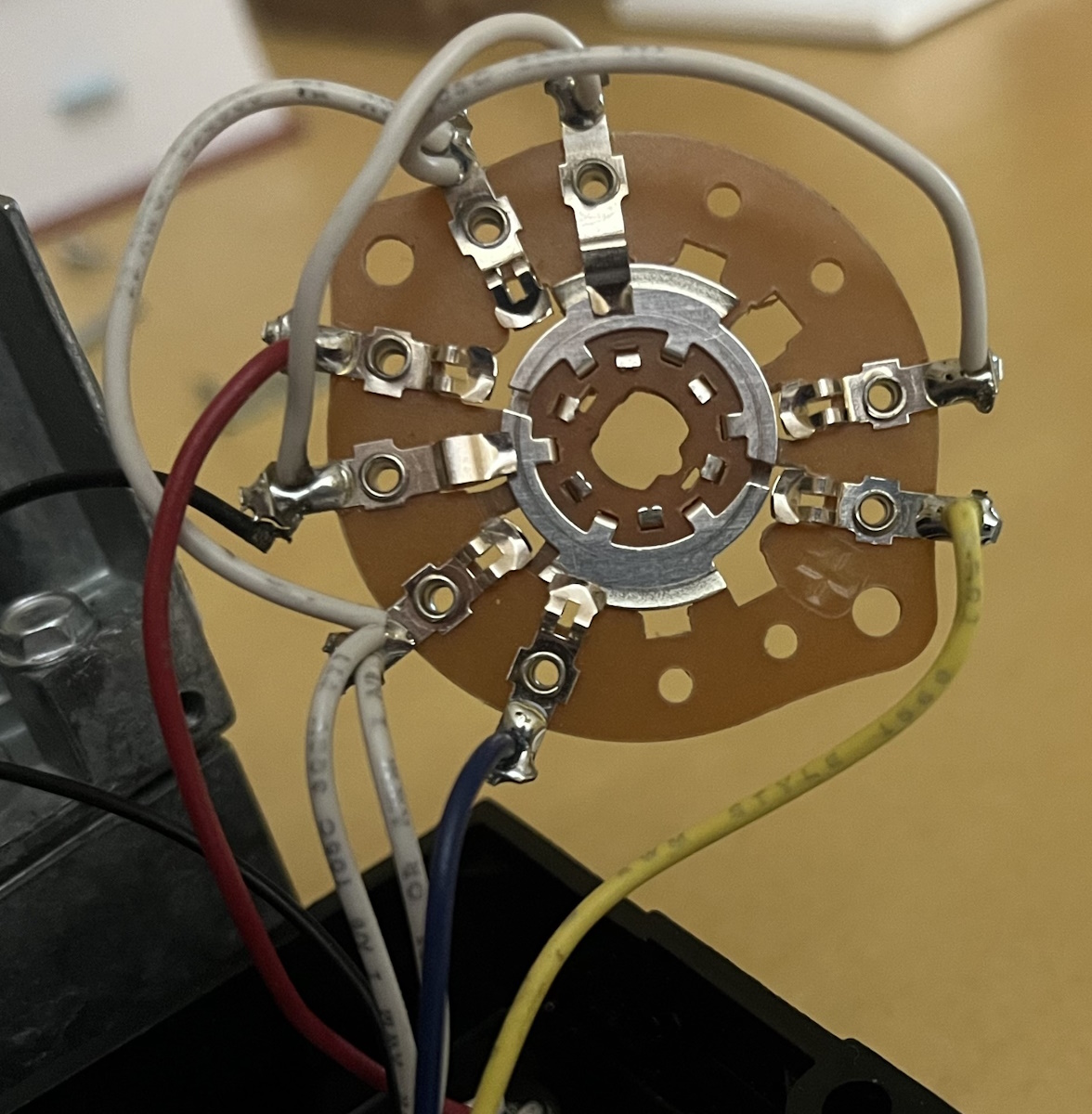
FIGURE 3: Pictured here in the closed position, the valve motor rotated another 90° and broke the auxiliary contacts for the burners. (Courtesy of Lianna Schwalenberg)
When the thermostat calls for heat again, the circuit is closed between 5 and 4 which sends power to the motor to start spinning again. After the motor stops spinning, it makes and maintains connection between 2 and 3, allowing for the auxiliary contacts to stay energized. The valve is open, and the process repeats when the thermostat is satisfied.
Table 1: White Rodgers 1300 Series Wiring Information
| Terminal | Purpose | Troubleshooting Notes |
| 1 | 24 V neutral, power for the motor | There should always be 24 V present between 1 and 2 from a transformer. |
| 2 | 24 V hot, power for the motor | |
| 2/5 | 24 V power for the thermostat | 2 and 5 are internally connected |
| 3 | 24 V power to energize the auxiliary circuit (the burner and/or circulator), between 2 and 3 when the valve opens. | If the same transformer powers the auxiliary circuit and the valve motor, connect auxiliary circuit to 1 and 3. |
| 4 | Thermostat makes switch between 5 and 4, energizing the motor. | Attach a jumper between 5 and 4 to force the valve to open. |
| 6 | Thermostat makes switch between 5 and 6, energizing the motor. | Attach a jumper between 5 and 6 to force the valve closed. |
Other Observations From Dissecting The Valve
Because the valve motor can be removed from the valve assembly, the technician can do a great deal of troubleshooting without draining the system. He or she can make visual observations of the parts most likely to wear out or break, such as the motor and the wire solder connections. The failure of the motor is the most likely cause of the valve to not change positions. There is a rubber O-ring on the valve stem which could wear out and cause leaking. This is the most likely scenario the technician would need to drain the system. The valve is entirely held together by screws, and White Rodgers does have part numbers to replace just the O-ring. The most legitimate reasons to un-sweat the valve would be to change its position or orientation.
The Fix
Recall that the valve does not move unless connections are closed within the thermostat. Three-wire valves of this style require special thermostats. The thermostat has to make a connection between terminals 5 and 4 on a call for heat, and it has to make a separate connection between terminals 5 and 6 when the call is satisfied.
There are many modern thermostats that can do this, but the technician must verify that the thermostat is compatible with “3-wire hydronic heat” or “3-wire zone heat.”
A regular thermostat, untampered with, will call for heat and the valve will open; however, taking away the call for heat will not cause this type of valve to move. In my particular case, the thermostat was wired 5 to R, 4 to W, 6 to G, and the fan switch was in the “On” position. Because the fan contacts were always closed, the valve was constantly receiving power to spin. Regardless of what position the fan switch is in, this stat will not work because there is nothing telling the valve to move again after the space temperature is met.
Looking for a reprint of this article?
From high-res PDFs to custom plaques, order your copy today!


