Troubleshooting Challenge: A Second Opinion on a Compressor Diagnosis
|
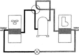
| Figure 1 |
In this month’s troubleshooting situation your customer is requesting a second opinion on a proposed repair to their air-source heat pump. The homeowner originally called for service when they noticed that the house wasn’t cooling down as they would like, and the technician who responded reported that since the high side and low side pressure differential wasn’t correct, the compressor was no longer able to pump properly. Due to the price of the proposed repair, the homeowner decided to call for a second opinion. Figure 1 shows a simplified illustration of the system.
When you arrive in the mid-afternoon, you confirm that both coil temperature splits are inadequate, and the system is unable to obtain the necessary comfort level. When you check the system pressures, you also note some irregularity, which prompts you to follow up with an entering and leaving test at the reversing valve tubing connections. Your results are as follows:
• Temperature on compressor discharge line: 200°F
• Temperature of discharge line exiting the reversing valve: 200°
• Temperature on line from indoor coil: 50°
• Temperature on compressor suction line exiting the reversing valve: 65°
Your troubleshooting question: What is the next step you need to take to repair this equipment?
Compare your answer with ours here.
Looking for quick answers on air conditioning, heating and refrigeration topics? Try Ask ACHR NEWS, our new smart AI search tool. Ask ACHR NEWS
Publication date: 7/6/2015
For information on Jim Johnson’s HVACR technician training DVDs, go to http://techtrainassoc.com/training-videos/hvacr-training-videos/.
Looking for a reprint of this article?
From high-res PDFs to custom plaques, order your copy today!


