Troubleshooting Challenge: A Split System with a Low Side Pressure Problem
|
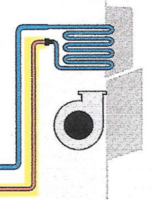
| Figure 1 |
In this troubleshooting situation a technician has responded to a complaint of “not cooling” on a six-year-old R-410A split system that employs an upflow gas furnace indoor air handler and a condensing unit that sits on the ground, and there is less than 20 feet of connecting tubing. An example of this piping configuration is shown in Figure 1.
A factory installed molecular sieve filter-drier is located inside the condensing unit. Upon the technician’s arrival, no apparent electrical or airflow problem was found that would result in the lack of cooling capacity, necessitating a check of the refrigeration system. Connecting to the low side only, the result was a pressure reading that would be considered far below normal. Based on that information, the technician decided to add refrigerant.
In a short time, the technician noted that while refrigerant is being added, there is no change in the low side gauge pressure reading. It remains the same no matter how much refrigerant is added, which leads to an inspection of the connecting tubing. At the indoor coil, the correct piping of the liquid line near the indoor coil employs a 90-degree ell along with a turn near the connection to the evaporator. Upon close inspection of this segment of tubing, it’s found to be cold to the touch.
Your troubleshooting question: After shutting the system down and recovering the refrigerant, what did the technician find in the above-mentioned section of liquid line piping?
Compare your answers with ours by clicking on the PDF link below.
Publication date: 5/4/2015
PDF - May Troubleshooting Answer
For information on Jim Johnson’s HVACR technician training DVDs, go to http://techtrainassoc.com/training-videos/hvacr-training-videos/.
Looking for quick answers on air conditioning, heating and refrigeration topics? Try Ask ACHR NEWS, our new smart AI search tool. Ask ACHR NEWS
Looking for a reprint of this article?
From high-res PDFs to custom plaques, order your copy today!


