Applications for Infrared Thermal Imagers

Thermal imagers can’t “see” through walls, but they can detect very fine differences in surface temperature that indicate air leakage, insulation gaps, moisture, and other structural issues.
[Editor’s note: This is part two of two in a series on infrared thermal imagers.]
Thermal imagers can be used for purposes where heat relationships are meaningful. They provide very fast, multiple-point temperature measurements of a scene. They are ideal for moving targets and machinery; hazardous, inaccessible, or distant targets; electrical components; big picture evaluations of machinery or surfaces; trending records; and even protection against litigation and insurance claims.
APPLICATIONS
Below are a few applications for thermal imagers:Duct leaks beneath insulation or in walls: When ductwork is located externally to the conditioned envelope, air leaks can present conditions for pressure differentials across the conditioned envelope, and create opportunities for moisture conditions that support mold growth in or on the ductwork or hidden within walls. The effects are similar to unbalanced ventilation and exhaust air. Below are some ways to apply a thermal imager in this case:
• Airleaks from ductwork beneath duct wrap insulation.
• Initiate a heating or cooling demand.
• Set emissivity to 0.2 for foil-faced insulation or 0.95 for vinyl- or PVC-faced insulation.
• Scan ductwork with thermal imager.
• Dynamic, real-time temperature variations of insulation surface will be displayed and continually updated as they occur.
• Indications of an air leak will be displayed as an extreme temperature at the point of the leak, with temperature gradation away from the leak location to areas of ambient temperatures.
• The imager can record selected images of interest for download, if desired.
• Air leaks from ductwork behind walls.
• Make an initial imager scan of walls concealing ductwork with the system blower off.
• Start the blower and repeat the initial scans.
• Compare results of blower-off to blower-on scans.
• Significant temperature deviations may indicate return leaks causing pressure differentials within the walls that encourage air and moisture migration from outdoors.
• Start heating or cooling operations.
• Repeat the wall scans.
• Even temperature gradients of the wall that follows the ductwork should be expected.
• Uneven or spreading temperature gradients may indicate leaking ductwork.
• Pay attention to temperature gradients along baseboards and around fenestration.
• The imager can record selected images of interest for download, if desired.
Diffuser discharge and surface effect ceiling temperatures:
• Start heating or cooling operation.
• Scan diffuser outward along ceiling toward intersecting walls or zones.
• Watch temperature change along ceiling to evaluate surface effect.
• Watch for temperature change at intersecting wall surfaces to evaluate throw.
• This provides a good preliminary analysis prior to breaking out the ladders and air balancing equipment.
• Throw should be 75-110 percent of distance from diffuser to intersecting surface.
Insulation effectiveness and air leaks:
• Insulation on all surfaces can be scanned for leakage and losses.
• Boiler, furnace, process equipment, and service water heater insulation.
• Walls that separate conditioned from unconditioned spaces.
• Pipe and duct insulation.
• Higher temperatures are indicated by a shift toward white.
• Lower temperatures are indicated by a shift toward black.
• Scan conditioned envelope walls or ceilings for even temperatures.
• Initial scan should be made with HVACR equipment off for insulation effectiveness.
• Subsequent scan should be made with blower, economizer, and exhaust fans operating to evaluate for air leaks.
• Economizers and power exhaust can be temporarily readjusted to increase.
• Pressure differentials across the conditioned envelope for testing purposes.
• Scan on both conditioned and unconditioned side of surface.
• Pay special attention to areas of fenestration and along sill plate areas.
Water leaks beneath membrane roofs: Rooftop HVACR equipment is often blamed when roof leaks appear, but tedious and time-consuming evaluations frequently dispel the accusations. Thermal imagers can be used to quickly track water beneath a membrane roof back to possible sources of entry.
• As the sun sets, water beneath the roof membrane changes temperature more slowly than areas of dry insulation under the roof membrane.
• Scan the roof surface and follow the higher temperatures to possible entry sources.
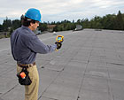
Cool
areas on this roof exposure probably indicate moisture buildup. Mark with tape
and investigate with core samples.
ELECTRICAL DEVICES
Thermal imagers can be used for a quick analysis of individual devices, or an array of contactors or relays in a control panel. From ground level, inaccessible transformer connections or line splices can be scanned for hot spots indicating high resistance of problematic connections. Panel bus connections can be quickly scanned for circuit integrity.Disconnects, contactors, relays:
• Scan disconnects, contactors, and relays for temperature consistency.
• All conductors connected to device should have equivalent temperatures.
• All mechanical connections to device should have equivalent temperatures.
• Circuit temperature and thermal characteristics of each pole should be consistent with the circuit temperature and thermal characteristics of the other poles.
• Movable contacts are likely to show higher temperatures than fixed connections.
• Specification data should provide the rated temperature rise of the device under full-load conditions.
• Wire insulation, paper covering of fuses, and insulated connections will be displayed as areas of higher temperature than uninsulated connections, bus bars, and bare wires due to the differences in material emissivity.
• A circuit within an enclosed relay will radiate heat to the casing. Relays under similar load should show similar heat patterns on the casing.
• Insulated conductors and electrical connections should be cool leading to and connected at the relays, contactors.
Line splices, power transmission connections, and transformer connections:
• Temperatures should be consistent along conductors’ lengths.
• Temperatures of splices or connections should be consistent with approaching and departing conductor temperatures.
• When disturbed by wind or branches, poor connections or splices can produce line transients that can affect the reliability and operation of equipment. Electronic devices are particularly susceptible to the effects of line transients.
Motors, bearings, sheaves, and belts:
• Motors can be scanned for operating temperatures within specifications.
• Bearings can be scanned for consistency of temperature.
• Bearings under equal load should display equal temperatures.
• A hotter bearing on the sheave side of the motor could indicate overtightened belts.
• Sheaves that are hotter around circumference could indicate slipping belts.
• Belts that do not cool between the motor and blower sheaves could indicate slipping belts.
Dynamic gas pressure within above-grade LP tanks:
• LP tanks must be sized for the load in order to evaporate sufficient gas while maintaining minimum pressures.
• Above-grade LP tanks can be scanned to estimate liquid level and vapor pressure.
• The heat of vaporization is extracted from the liquid LP.
• When demand is high, the horizontal line of temperature change on the outside of the tank will approximate the liquid level within the tank.
• The liquid LP absorbs heat from the ambient air through the tank walls.
• The tank surface temperature pressure corresponds to the vapor pressure in the tank. If a P-T chart for LP gas is not available, a P-T chart for R-22 can be used to get a ballpark estimate of the pressure. R-22 pressures below freezing are usually about 4 pounds less than LP gas pressures at equivalent temperatures.
“All points” operating temperatures of compressors:
A thermal image snapshot of an operating compressor (or other machinery) can be saved in a trending or maintenance record. The image will contain operating temperatures of all points in the image such as sump temperature, head temperature, suction and discharge temperatures, etc. Ambient and operating conditions should be saved along with the image.
Steam traps, lines, radiators, and convectors:
• Thermal imagers are ideally suited for assessments of steam heating processes. They can quickly see the trap and line temperatures into and out of traps. They can be used to follow pipe temperatures to the source of problems.
• If the temperature is low in the steam pipe, low in the trap, and low in the condensate return, the trap may be stuck closed.
• If the temperature is high in the steam pipe, high in the trap, and high in the condensate return, the trap may be stuck open.
• If the temperature is high in the steam pipe, high in the trap, and slightly lower in the condensate return, the trap is probably operating properly.
Tracking hydronic radiant heat loops: Thermal imagers can be used to track radiant loops under solid surfaces. The radiant loop should show a similar palette gradient along the loops. Loop temperatures can be temporarily elevated for tracking purposes.
Air-to-air condenser or evaporator circuitry:
• A thermal snapshot of condenser or evaporator return bends, or distributor tubes, can find circuit problems much more quickly than using contact thermometers for the same task.
• Each circuit will condense or evaporate refrigerant at a constant temperature.
• Subcooling or superheat should be equivalent in the last passes of each circuit.
• All distributor tubes should be at evaporating temperature.
CONCLUSION
This introduction to thermal imagers is offered to give potential users some insight to typical applications, and may spark ideas for additional uses. For instance, a routine walk-through of a facility with a thermal imager showing real-time movies of critical machinery or processes is not only easy and time saving, but can alert the user to processes that warrant further attention.For information on building envelope leak testing, refer to ASTM Standard E1186-03, Standard Practices for Air Leakage Site Detection in Building Envelopes and Air Barrier Systems, and ASTM Standard E779-03, Standard Test Method for Determining Air Leakage Rate by Fan Pressurization.
Publication date: 06/14/2010
Looking for a reprint of this article?
From high-res PDFs to custom plaques, order your copy today!


