Troubleshooting Tips for Heat Pump Reversing Valves

SWITCHEROO: Being able to troubleshoot a heat pump reversing valve can save time, money, and frustration.
A heat pump functions as a typical air conditioning system in the cooling mode — absorbing heat from indoors and rejecting it outdoors. In heating mode, the coils reverse their functions. The outdoor coil becomes the evaporator, and the indoor coil becomes the condenser. Now the heat pump is moving heat from outside the structure to the inside.
The reversing valve is responsible for this change in operation by changing refrigerant flow between the indoor and outdoor coils. Changing the direction of refrigerant flow means that the indoor and outdoor coils change function. When the flow changes, it also changes the direction of flow through the other refrigerant components: dryer, metering device, check valves, and so forth.
In most units, the reversing-valve solenoid is energized during the cooling cycle, but in some, it is energized during the heating cycle. Since heat pumps are typically not the sole heat source, many manufacturers opted to default to the cooling mode.
Reversing Valve Mechanics
Figure 1 shows the exterior view of a reversing valve. The single-tube connection is always connected to the compressor discharge. The bottom middle connection must be connected to either the compressor suction line or, when an accumulator is in the circuit, this connection is to the accumulator inlet. The accumulator outlet is then connected to the compressor suction. This puts the accumulator upstream from the compressor and protects it in either the heating or cooling mode.

FIGURE 1: Exterior view of a reversing valve. (Courtesy of ACCA)
Troubleshooting
If the solenoid coil is energized in cooling, a faulty solenoid coil will cause the unit to operate in the heating mode anytime the compressor runs. If the solenoid coil is energized in heating, a defective solenoid coil will cause the unit to operate in cooling mode anytime the compressor operates.
Before checking the position of the valve operation, the electrical control system should be examined to determine the operating requirements of the valve. For example, the O terminal on the thermostat usually energizes valves that operate in cooling. In contrast, valves energized in heating are typically energized by the B terminal on the thermostat.
Problems in reversing valves are either electrical or mechanical. Electrical issues are typical of the solenoid coil on the pilot valve. When the solenoid coil is energized, and nothing happens, test the coil as follows:
Looking for quick answers on air conditioning, heating and refrigeration topics? Try Ask ACHR NEWS, our new smart AI search tool. Ask ACHR NEWS
- Feel the solenoid coil. If it feels hot, the coil is energized.
- Verify that voltage is applied to the solenoid coil. Some systems have the coil in the 240V portion of the system, while others use it in the 24V portion. Consult the wiring diagram for coil voltage before applying the leads of the voltmeter. Start the test with the voltmeter set to the higher range. This can reduce meter damage.
- With voltage applied to the solenoid coil, remove the coil holding nut, and attempt to pull the coil off the pilot valve plunger casing. If you feel resistance to removing the coil, the coil is active. (See Figure 2.)
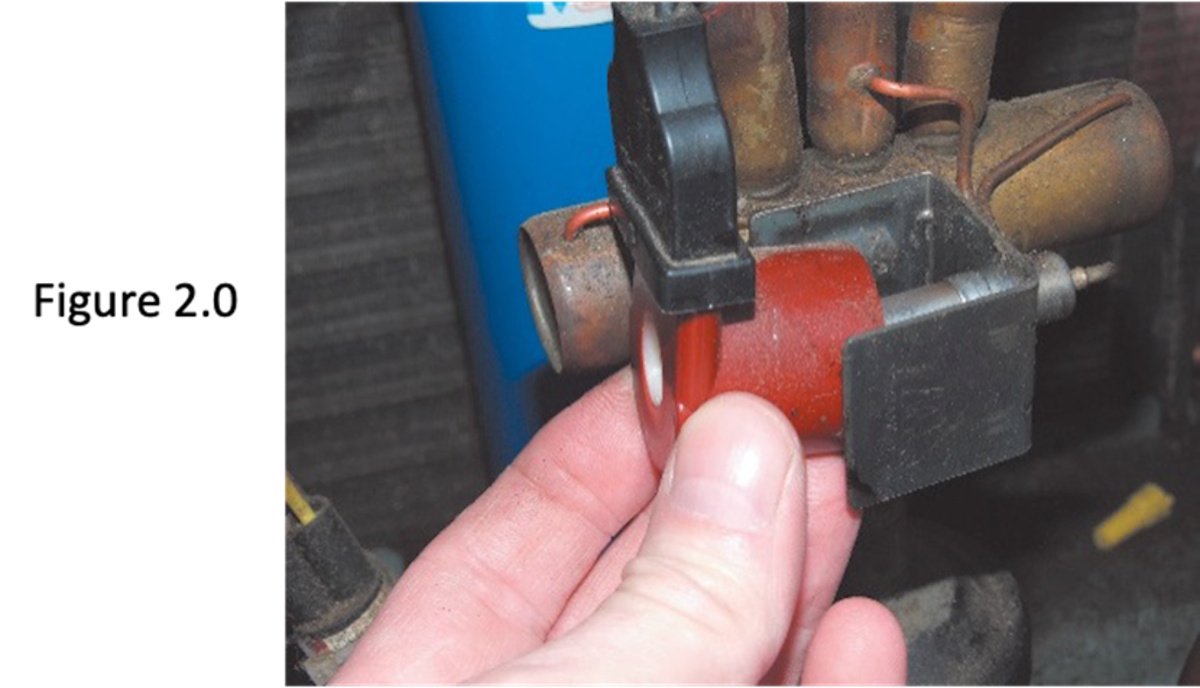
FIGURE 2: To determine whether a coil is active, apply voltage to the solenoid coil, remove the coil holding nut, and attempt to pull the coil off the pilot valve plunger casing. Resistance to removing the coil means the coil is active. (Courtesy of ACCA)
- If no pull is felt, shut off the power, remove the coil heads, and check for continuity with the ohmmeter. (See figure 3.) If open, replace the coil. If a circuit exists, check the leads and the connections for continuity.
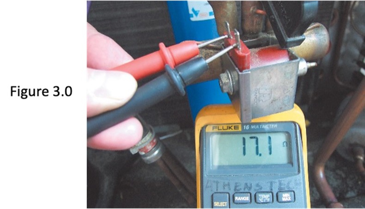
FIGURE 3: If no pull is felt, shut off the power, remove the coil heads, and check for continuity with the ohmmeter. (Courtesy of ACCA)
- If the solenoid coil is active, a click should be heard when the pilot plunger returns to the normally closed position when removing the coil. If no clicks are heard, the pilot valve is stuck. The only repair is to replace the reversing valve.
When the pilot valve checks out satisfactorily, and the main valve does not shift, ensure that suction and discharge show more than a 100 PSIG difference. If the valve is in the cooling position, block off the air to the condenser with plastic on the inlet face of the coil. Allow the unit to operate until the condensing saturation temperature rises to 130°F. With the unit running, cycle the valve on and off several times. This will usually free the main valve to operate again. If no results are achieved, change the valve.
Leaking Reversing Valves
A heat pump operating with a leaky reversing valve will have the same symptoms as a system with an inefficient compressor. Therefore, a leak test on a reversing valve is executed. This is to determine if the valve is leaking from discharge to suction. Temperature measurements are used to determine leakage. (See figure 4.) This example checks the reversing valve for leakage from the high side to the low side. Keep in mind, the reversing valve may leak in one mode and not the other.
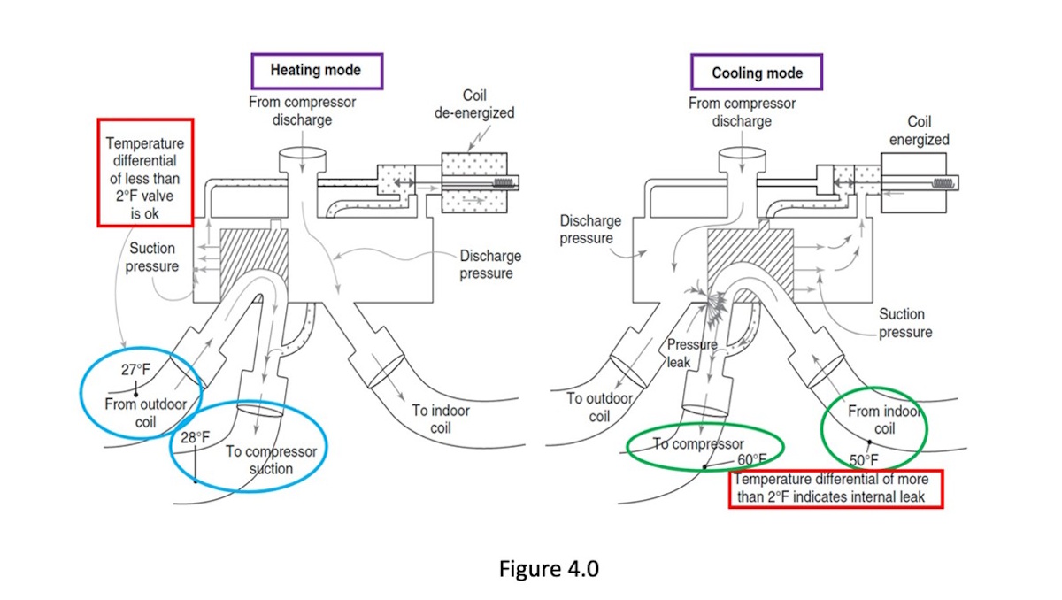
FIGURE 4: A leak test on a reversing valve. (Courtesy of ACCA)
The refrigerant charge in the system is not lost when the reversing valve develops an internal leak. This is because an internal leak transfers the refrigerant from one section of the system to another. This occurs without refrigerant escaping to the atmosphere.
However, more significant leaks within a reversing valve can result in numerous problems, such as:
- The compressor overheating and premature failures.
- Lower-than-normal head pressure.
- Higher-than-normal suction pressure
- Reduced suction gas cooling.
- Reduced effectiveness in the heating mode.
- Reduced cooling capacity in the cooling mode.
Touch Test
An internal leak in the reversing valve can be detected easily by taking temperature readings at strategic locations in the system, primarily at the port connections on the reversing valve itself. This is often referred to as a touch test. This test is generally more accessible if you have Bluetooth temperature measuring tools to provide accurate readings. You may also use an infrared thermometer. If you choose to use an infrared thermometer, consult the manufacturer's instructions to understand its limitations.
Figure 5 shows a typical four-way reversing valve and temperatures of the ports during heating and cooling mode operations. Caution: It should be understood that touching the discharge ports will be extremely hot. Discharge = hot!
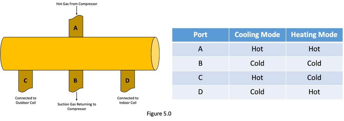
FIGURE 5: A typical four-way reversing valve and temperatures of the ports during heating and cooling mode operations. (Courtesy of ACCA)
In the cooling mode, Port A should be hot, while Port B should be cold. This is because ports A and B are exposed to the discharge refrigerant, leaving the compressor and the suction gas returning to the compressor. Port C should be hot as well, since the discharge gas is leaving the valve from this port. Port D should be cold, since the suction gas from the evaporator is entering the reversing valve at this point.
Ports A and D should be hot in the heating mode because the hot discharge gas flows through both of these ports. Conversely, ports B and C should be cold while operating in the heating mode.
By evaluating the temperatures at these points on the valve, the technician can quickly determine if the four-way reversing valve is operating correctly.
Conclusion
A service technician must have a complete understanding of the function of the reversing valve. Being able to troubleshoot this vital piece of equipment can save you time, money, and frustration. Unfortunately, many times reversing valves are misdiagnosed, and this leads to unnecessary repairs or, worse yet, throwing parts at a heat pump until the issue is resolved — if it ever is. When diagnosing a reversing valve, follow these steps to help you along the way. Once you have a diagnosis, you can put options together for your clients to make an informed decision on how they want to proceed with repairing their heat pump or give consideration to a system upgrade.
Looking for a reprint of this article?
From high-res PDFs to custom plaques, order your copy today!


