Hydronics Zone: In Over Your Head
Radiant ceilings are a great option in many systems
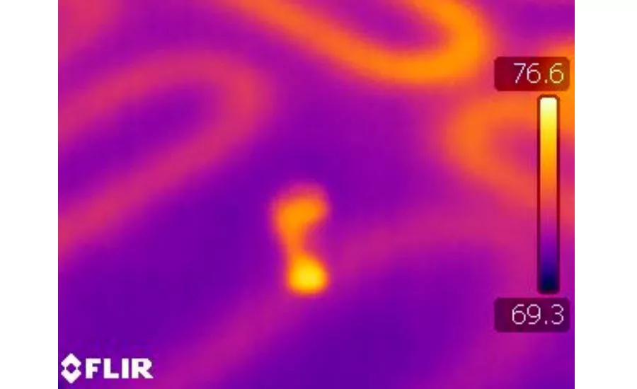
FIGURE 1

FIGURE 2.
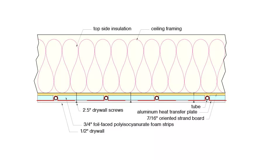
FIGURE 3
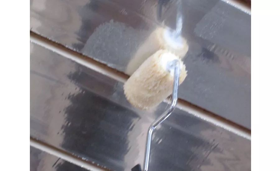
FIGURE 4.
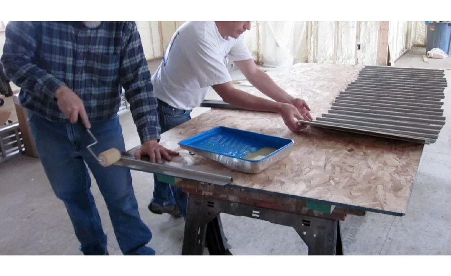
FIGURE 5.
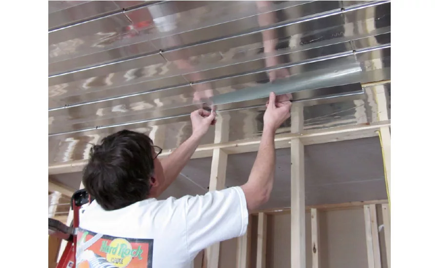
FIGURE 6.
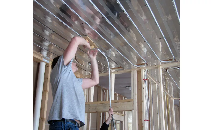
FIGURE 7.
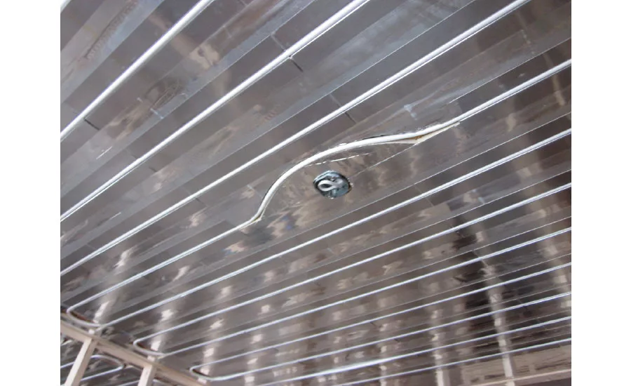
FIGURE 8
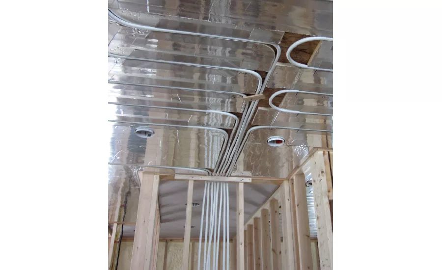
FIGURE 9.
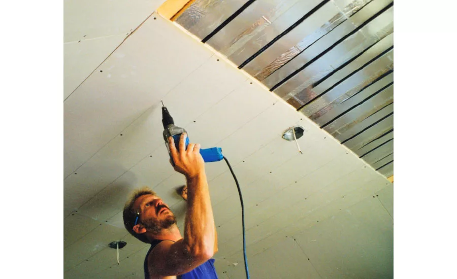
FIGURE 10.
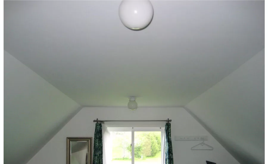
FIGURE 11.
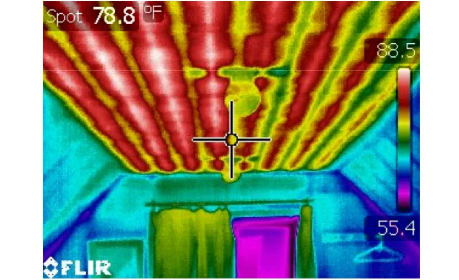
FIGURE 12.
Ask almost anyone in the heating trade about radiant panel heating and they’ll probably start describing tubing embedded in floors. Radiant floor heating is by far the biggest part of the radiant panel market. It’s an excellent approach in many projects ranging from residential all the way up to heavy industrial applications. However, it’s not necessarily the ideal solution for the coming generation of low-energy-use homes.
When viewed only from the standpoint of heat source performance, the low operating temperature of a bare concrete slab with closely spaced tubing (6- to 9-inch spacing) is very beneficial. A well-insulated house on a design day may only require supply water temperatures in the 85°-90°F range to maintain the interior space at 70°. Condensing boilers, solar collectors, and hydronic heat pumps all love to operate at these low temperatures and show their gratitude by operating near the upper end of their performance range.
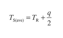
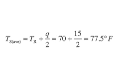
That’s the good news. The downside is two-fold: First, the average floor surface temperature required of a heated floor in a well-insulated house is only a few degrees above the room temperature. You can estimate this average floor surface temperature using this formula:
Where:
TS(ave) = average floor surface temperature (°F)
TR = room air temperature (°F)
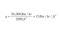
q = upward heat flux from floor (Btu/hr./ft2)
For example, imagine a house with 2,000 square feet of heated floor area and a modest design heat loss of 30,000 Btuh. The required upward heat flux under design load conditions is:
Assuming the room air temperature was to be maintained at 70°, the average floor surface temperature would be:
This temperature is at or slightly below normal bare-skin temperature. In such a case, heat would be conducting from the foot or hand to the flow, as shown by the infrared image in Figure 1. During most of the heating season, the floor surface temperature would be even lower, perhaps around 74° when the outdoor temperature is 35°.
True, the floor is still warmer than it would be with convective-type heating. But, it may not be delivering the barefoot-friendly effect so widely advertised as a benefit of radiant floor heating. The fact that the room is still maintained at 70° is unlikely to placate the unmet customer expectations of warm-to-the-touch floors.
Looking for quick answers on air conditioning, heating and refrigeration topics? Try Ask ACHR NEWS, our new smart AI search tool. Ask ACHR NEWS
The other drawback is thermal response. Low-energy-use homes are especially susceptible to rapid temperature changes from internal gains. In many new homes, this is further exacerbated by above-average passive solar heat gains.
These characteristics don’t bode well for high-mass heat emitters, such as heated concrete slabs. Spaces will quickly overheat when the sun comes out and much of the solar gain will be lost through the ventilation necessary to keep the house from turning into a sauna.
LOOKING UP
Low-energy-use homes need heat emitter systems capable of rapidly changing their rate of heat delivery. Think Jet Ski rather than oil tanker. One good candidate is a low-mass radiant ceiling panel. Heated ceilings deliver more than 90 percent of their heat output as thermal radiation. They “shine” thermal radiation down into the room, much as a light fixture shines visible light downward. They offer several benefits:
• Low Thermal Mass — Low-mass radiant ceilings can quickly warm up following a cold start. They are ideal in rooms where quick recovery from setback conditions is desirable. Low mass also means they can quickly suspend heat output when necessary. This helps limit overheating when significant solar heat gain occurs.
• Higher Heat Output — Because occupants are not in contact with them, radiant ceilings can be operated at higher surface temperatures than radiant floors. This allows greater heat output per square foot of ceiling. For example, a ceiling operating at an average surface temperature of 102° releases approximately 55 Btuh per square foot into a room maintained at 68°. This is almost 60 percent more heat output than a radiant floor with a mean surface temperature limit of 85°.
• Not Affected by Changing Floor Coverings — It’s probably safe to say the days of shag-carpeted ceilings are over. Ceilings are the least likely surface of a room to ever be covered, especially by anything with high thermal resistance. Thus, the output of a heated ceiling is very unlikely to be compromised by surface coverings or furniture placement.
• Warms Objects in the Room — The radiant energy emitted from a heated ceiling is absorbed by the surfaces in the room below. This includes unobstructed floor area as well as the surfaces of objects in the room. The upward-facing surfaces tend to absorb the majority of the radiant energy; the top of beds, tables, and furniture are slightly warmer than the room air temperature. The surface temperature of floors below an active radiant ceiling will be slightly warmer than they would be if the room was heated by convection.
• Easy to Retrofit — Radiant ceilings are usually easier to retrofit into existing rooms than radiant floors. They add very little weight to the structure and require minimal loss of headroom.
Figure 2 shows one construction detail we’ve used to build a low-thermal-mass panel using standard construction materials, ½-inch PEX-AL-PEX tubing, and aluminum heat-transfer plates.
Figures 3 through 10 show several stages of installation for this radiant ceiling panel.
Figure 3 shows ¾-inch-thick foil-faced polyisocyanurate foam insulation strips ripped to 7 ¼-inch width and bonded to 7/16-inch-oriented strand board sheets using contact adhesive. The OSB sheets are nailed to the ceiling framing to provide a flat “screw base” material for the balance of the system.
The foam insulation is held back in locations where a 180-degree return bend in the tubing will be located. You also can see it’s no big deal to go around ceiling junction boxes. If 1 ¼-inch-deep junction boxes are used, they can be directly screwed to the underside of the OSB. If deeper boxes are needed, they will have to be fastened above the OSB and projected through a cutout in the OSB.
Figure 4 shows a 3-inch roller on a pole handle being used to place contact adhesive on the foil facing. This adhesive is only placed on one side of each ¾-inch groove. This important detail allows the aluminum heat-transfer plates to expand slightly when the tubing is eventually pushed into place.
Figure 5 shows how the contact adhesive is rolled onto one rear side of each heat-transfer plate. A quick pass or two with the roller is all that’s required. These plates are light, and a little contact adhesive goes a long way.
Figure 6 shows the plates being pressed into place against the foil-faced foam strips. This is where the two surfaces coated with contact adhesive meet and instantly bond. It’s important to hold the plate so the tubing groove is tight against the edge of the foam on the side with the adhesive. This allows a very slight expansion space on the other side of the tubing groove for when the tubing is pressed into position. It also keeps all the grooves neatly aligned.
Figure 7 shows an installer putting ½-inch PEX-AL-PEX tubing in place. A person on the floor feeds the tubing upward, keeping it aligned with the grooves. The person near the ceiling is using a wooden float to push the tubing up into place. This is a lot easier and ergonomically acceptable compared to pounding the tubing in place with your palm.
Figure 8 shows tubing in place, along with a “detour” around a junction box. Just leave the plates out in this area.
In this particular project, the manifold stations for the radiant ceiling circuits are located in the basement. This is much easier than trying to locate them in the attic. Each circuit has a “riser” on supply and return that is routed down through interior studded walls, as seen in Figure 9.
When the system is equipped for a good forced-water purging and includes a microbubble air separator, there is no problem getting the air out of the ceiling circuits and keeping it out.
The final step is to install ½-inch drywall using 2 ½-inch screws driven on 12-inch spacing in rows spaced half way between the tubes, as seen in Figure 10 (from another project). These screws will “squeeze” the assembly a bit and help ensure good contact between the bottom of the aluminum plates and the back side of the drywall.
Finish the drywall in the normal manner. When completed, there is no visual indication the ceiling will soon be a luxurious radiant panel.
EXCELLENT PERFORMANCE
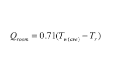
The heat output of this ceiling can be estimated using this formula:
Where:
Qroom = heat transfer rate to room side of ceiling (Btuh per square foot)
Tw(ave) = average water temperature in the wall circuit (°F)
Tr = room air temperature (°F)
Here’s an example: Determine the heat output of this radiant ceiling if operating at an inlet water temperature of 115°, a circuit temperature drop of 10°, and supplying heat to a room at 68°.
The average water temperature in the panel would be 115 – 10 / 2 = 110°. Now, plug the numbers into the formula on Page 18 and run them through your calculator.
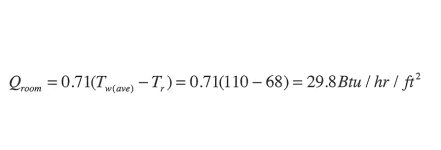
This output is almost twice the 15 Btuh per square foot required for the low-energy-use home in the first example. The implication, for this case, is that 1 square foot of heated ceiling could supply the heat for almost 2 square feet of floor area. This means less material and a lower installation cost compared to filling the floor up with tubing.
This low-temperature performance makes this radiant panel well-suited for systems with mod/con boilers, as well as for systems using renewable energy heat sources, such as solar collectors and hydronic heat pumps.
Figure 11 shows a finished radiant panel ceiling constructed using the details shown earlier. It is indistinguishable from a standard drywall ceiling. However, the infrared thermal image of the same ceiling area, shown in Figure 12, indicates this is no ordinary ceiling.
The infrared image in Figure 12 was taken about 10 minutes after warm water began flowing through the single ceiling panel circuit. The red stripes on the left side of the image show excellent lateral heat diffusion by the aluminum plates. The strips also are evidence that these plates are making good contact with the back of the drywall. Can you tell which direction the flow is moving across this ceiling?
If you’ve never tried a radiant ceiling panel, I urge you to do so. I’ve used this panel construction on several projects and have always been delighted with the installation method, performance, and lack of problems. By the way, with suitable system controls, this ceiling panel is ideal for radiant cooling applications.
Publication date: 2/15/2016
Want more HVAC industry news and information? Join The NEWS on Facebook, Twitter, and LinkedIn today!
Looking for a reprint of this article?
From high-res PDFs to custom plaques, order your copy today!


