Evap Tube Results In Ammonia Leak

The refrigeration system's evaporators were located in small rooms, or annexes, adjacent to the storage rooms. The evaporators were manufactured from aluminum tubes, welded at their ends to form U-bends. Fans circulated cold air between the small evaporator annex rooms and the storage rooms.
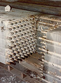
The ammonia leak was observed to originate from the evaporator coils in the annex to room P-3. Figure 1 shows the evaporator that had been leaking; the discolored area had been indicated as the source of the leak. The evaporator in the P-3 annex had been in operation for about six years.
Other areas of discoloration on the evaporator coils and fins appeared to be less recent. These marks seem to have been caused by corrosion of steel components above the aluminum evaporator coils.
The operator of the cold storage facility said that a previous failure had occurred in this coil. The failure, he said, was caused by a fan separating from its housing, striking the coils. The repair consisted of plugging the damaged tubes. It is not known when this failure and repair occurred within the lifetime of the evaporator.
The general area of the ammonia leak was identified during an initial inspection of the coil in place; however, the faulty tube could not be identified. We recommended that the coil be removed from the system and leak tested.
LEAK TESTING
The subject evaporator coil was removed from the annex of P-3. It measured 18 feet long by 8 feet wide by 2 feet high. The coil was made of 3/4 inch outside diameter aluminum tubes.The wall thickness of the tubes measured 0.05 inches thick. Initial leak testing to a pressure of 250 psig revealed the presence of a leak four feet from the end. So, we removed a 20- by 20-inch full-thickness section of the coil for further disassembly to find the origin of the leak, (Figure 5). We disassembled the removed section and performed further testing of the individual tubes; that testing revealed no leak.
It did, however, reveal that five of the 80 aluminum tubes in the removed section were sleeved. The internal tubes measured 5/8 inch outside diameter, and were also made of aluminum. The sleeved tubes appeared to be discontinuous; they did not run the entire length of the evaporator, and it looked like they were made up of one or more shorter-length sections. The sleeve sections were neither sealed to each other nor to the inner tube, and a small gap existed between their ends.
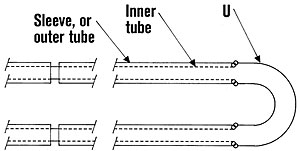
Figure 3 shows a schematic drawing of a typical sleeved tube; it consists of an outer tube or sleeve constructed in two or more sections, as previously described. The inner tube is continuous and of a smaller diameter than the outer tube. The sleeve and inner tube are welded together only at each end of the evaporator to a U-shaped piece (Figure 4).
Looking for quick answers on air conditioning, heating and refrigeration topics? Try Ask ACHR NEWS, our new smart AI search tool. Ask ACHR NEWS

We further examined the tubes, and found abnormal bulging of each outer tube at its intersection with the U-bend at one end of the evaporator (Figure 7). We conducted on-site leak testing of the evaporator to determine the precise location of the leak. This required repairing the previously cut section, and ultimately proved to be difficult and inconclusive.
We needed to remove a second section of the evaporator containing the U-bends and bulged tubes. This section was taken to the lab for further examination and testing. Figure 5 shows the location of the second removed section.

LAB TESTING
The second removed section, as mentioned, included the U-bends. The bulged tubes were numbered for identification.

The weld fracture in the subject tube and U-bend does violate the integrity of the system, and would permit an ammonia leak at this location. The leak however would not be evident at the location of the fracture because of the surrounding outer tube or sleeve. The ammonia would find its way to the gap between the outer tubes, and appear as a leak here, four feet away from the actual fracture.
The leak rate for the fracture was measured, then plotted versus pressure. At 250 psig, the predicted leak rate is 4.3 cfm. This is a significant leak rate, and is consistent with the reported damage.

THE FRACTURE SURFACE
The fracture surface of the tube and U-bend was further sectioned and mounted for microscopic examination. Examination of the fracture surface with a scanning electron microscope revealed the presence of ductile dimples, suggesting that the fracture mode was mechanical overload and not progressive fatigue damage or corrosion. Further examination of the fracture also revealed the presence of minor porosity in the weld. The porosity likely did not contribute to the failure.The ammonia leak in the subject evaporator originated at a weld between a sleeved tube and its matching U-bend at the end of an evaporator unit. The leak was due to a weld fracture that showed evidence of mechanical overload.
Based on the knowledge that the evaporator is used in a water vapor environment, water condensing on the tubes and turning to ice during normal operation melts during a refrigeration shutdown or defrost cycle. Reportedly the defrost cycle is conducted manually, and water is also sprayed on the evaporator tubes to accelerate the process. Water, either from melting ice or spray likely entered between the walls of the sleeved tubes at the sleeve junction, and migrated to the weld area. When the refrigeration cycle started over, the water collected near the weld, froze, and expanded in the restricted area.

Did those rose roots have to die? Probably not. This condition was allowed to exist because of the gap between the two adjacent sleeve sections. The use of this two-section sleeve during the construction and fabrication of the evaporator was the initiating cause of the weld failure and subsequent ammonia leak.
The use of the two-section sleeve for use in a water vapor environment is not appropriate. It promotes the trapping of water between the sleeves. When the trapped water freezes, it creates enough force to rupture the tubes and produce a refrigerant leak.
Dirk H. Duffner, P.E., is a founder and one of the managing members of Principia Engineering Services, San Francisco, Calif. He specializes in failure analyses of materials and mechanical systems, focusing on determining the root cause of failures in a wide variety of products. He may be reached at dduffner@principia-eng.com.
Publication date: 01/23/2006
Looking for a reprint of this article?
From high-res PDFs to custom plaques, order your copy today!


