Btu Buddy 182: Lunch Time Session on Chiller Service
Bob and Tim are at lunch and discussing the last service call that they had which was a spring start up on a 100 ton chiller. Tim has some questions about how a chiller operates and Bob is filling him in on some blank places that he has in his knowledge base.
Bob explains, “All mechanical refrigeration systems work basically alike. As we discussed in the last service call a chiller cools water and circulates water through the building and back to the chiller. Typically a chilled water system will operate at about 45°F water leaving the chiller and returning to the chiller at 55°F, thus a 10° drop through the chiller. This only occurs when the chiller is working at full load. Most chillers have the ability to run at partial load so that they won’t have to stop and start so many times. If you can imagine a 100 ton system that would reduce the building temperature to the setpoint and then shut down, and then stand idle until the building warmed up a little bit and then start back up again. That’s a large piece of equipment that is stopping and starting on the electrical line. Manufacturers have developed several ways to offer capacity control.
"The chiller that we worked on had four steps of capacity control. It would start up as a 25 ton chiller, then more cylinders would start pumping and make it a 50 ton chiller and then two more cylinders would cut in making it a 75 ton chiller and then the last step would be another two cylinders start pumping and the chiller would become a 100 ton chiller. As the building cooled the chiller went backwards through the steps, to 75, 50, and 25 tons of cooling. If the building temperature continued dropping, the chilled water temperature would continue to drop and the chiller would shut down while operating at 25 tons. As the water temperature in the building starts to rise, the chiller would start up at 25 tons and go back up through the various tonnages. It is conceivable that a chiller would start up in the morning and run all day without stopping only varying the capacity of the chiller to match the load of the building."
Bob then explained, Tthe condenser portion of the chiller is very similar to the chilled water portion of the chiller with some exceptions. The condenser portion of the chiller is an open circuit with the cooling tower on the other end which can allow contaminants from the atmosphere to get into the condenser water circuit and foul the water. The chiller portion of the circuit is a closed loop and likely will not have to have a change of water for years. Water is charged into the system with a treatment to maintain the water that just circulates over and over again with water being added automatically if there is a leak.
If you’ll remember that the service call that we were just on we spent all of our time working with the condenser side of the circuit and servicing the water and cooling tower. The water in the chilled water the side of the circuit maintains itself unless a large leak occurs.
Now let’s move on to what happens if the chiller has some sort of problem. How do we troubleshoot the entire chiller. When we are troubleshooting air cooled equipment we are pretty well assured of knowing what the airflow is through the condenser side of the circuit because it is all a factory installation with a fan and a coil. When we are troubleshooting a chiller we now have two portions of the chiller we need to pay attention to, the chilled water flow rate and the condenser water flow rate. The chilled water flow rate is more likely to be a constant and the condenser water flow rate is more likely to have a variable due to a strainer being installed in the water flow which will catch any trash that’s picked up from the cooling tower and circulating in the system. Let’s approach the system one component at the time and let’s work with the chilled water circuit first.
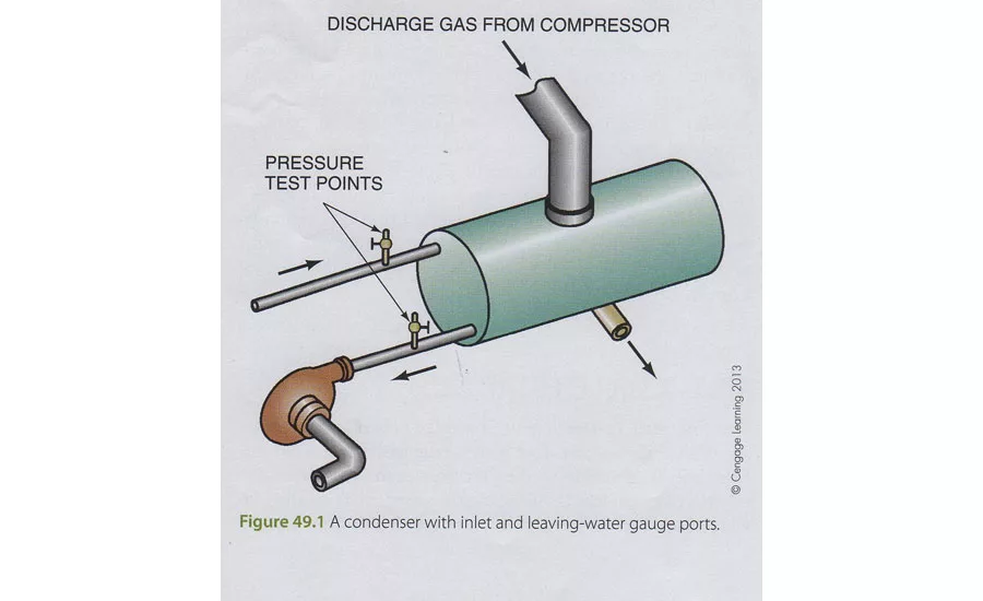
Every chiller is furnished with a data sheet that tells you what the chilled water flow should be through the system for the particular building that you’re working with. In the field the way you check the water flow is by taking an accurate reading of the water pressure drop from the inlet to the outlet of the chiller barrel. You will notice that there are pressure gauges on either side of the chiller in the water piping. You will also notice that the pressure gauges have a small valve that you can open to get a reading of the particular pressure gauge.
Looking for quick answers on air conditioning, heating and refrigeration topics? Try Ask ACHR NEWS, our new smart AI search tool. Ask ACHR NEWS
(Figure 1) Through very rigorous and thorough test procedures, manufacturers determine what the water flow is through a chiller barrel or any heat exchanger for that matter, in gallons per minute based on the pressure drop across the heat exchanger. Most pressure gauges that are in operation for long periods of time are not really accurate. As you will notice the needle wiggles back and forth, this creates wear within the mechanism and you can’t really rely on this gauge being accurate. The question here is what is the pressure drop from one side of the chiller barrel to the other with the chilled water pump running. The best way to determine this is to take a single pressure gauge, preferably of a larger diameter gauge and check the pressure entering the chiller by closing the little valve removing the field gauge and installing your personal service gauge and taking a reading. Then unscrew the field gauge from the outlet of the chiller barrel and screw your test gage in the outlet and take a reading at that point with the same gauge. The reason for this is if you use the field gauges, each one of them may have a 1 psi error in it and if one reads high and one reads low you have a 20 percent error at a 10 psi pressure drop. If you use the same gauge for the inlet reading and the outlet reading you minimize this possibility to practically nothing. Since we don’t have a data sheet on this chiller, we will assume that the pressure drop across the chiller should be about 10 psi. Now take the readings and see what you see."
Tim took the readings and said, “Sure enough there is an 11 psi difference from the inlet to the outlet. I’m assuming this is okay”.
Bob then explained, “If the pressure difference between the inlet and the outlet began to drop, it would be a sign of reduced water flow. If the chiller is running at full load and the water flow started reducing we would also notice the temperature difference would rise because you are removing the same amount of heat from a reduced water flow which would, cause a temperature increase across the water heat exchanger. For example, if you normally had a 10° drop across the chiller from 55° to 45° and you noticed that the temperature drop went to 55° to 43° that becomes a 12° difference. The suction pressure would also be dropping at the compressor inlet as well as the refrigerant boiling temperature in the chiller barrel. If the temperature is dropping, the chiller would soon be operating below freezing. In this case there is a freeze control to shut the chiller off to prevent freezing. Knowing what the design operating temperature of the chiller is supposed to be gives you the guidelines to know when the chiller is drifting out of the design conditions."
Bob then went on to explain that now that we have talked about the chilled water side of the system which normally never gives a problem. We will move on to the condenser water side where most problems occur.
Tim then said, “It’s nice to be able to divide the system up to the evaporator side in the condenser side and understand each side so that you can spot trouble easier."
Bob then said, “The condenser side of the system has a lot of similarities to the chiller’s. Normally the water pressure drop across the condenser is similar to the water pressure drop across the evaporator. Since we don’t know what that design pressure drop is in some installations, we will assume it should be about 10 psi drop from inlet to outlet. It’s always nice to have a data sheet on the chiller, but it is also often that you cannot find the data sheet. When the equipment was started up, the startup technician should put that data sheet inside the console for the chiller but oftentimes they don’t.
You would want to do the same thing with the condenser water flow that you did with the chilled water flow, check the pressure drop with the same gauge from inlet to outlet to get the most accurate reading. When the chiller is running, at full load, you can check the temperature rise across the condenser and it should normally be about 10°F. That’s a good starting point when you don’t know what it really should be.
Now let’s talk about problems that could happen to the chiller. The most likely problem is a dirty condenser. When we look at the gauge reading and the head pressure is higher than normal we would suspect a dirty condenser. One of the first things that we should notice with a dirty condenser is a hot liquid line. The design temperatures and pressures on a typical condenser would be;
- 85°F and inlet condenser water temperature.
- 95°F leaving condenser water temperature.
- 105°F refrigerant condensing temperature Head Pressure 210 psi for R-22.
- Approach temperature 10°F. The approach temperature is a value that shows how close the condensing refrigerant temperature approaches the leaving condenser water temperature.
These are guidelines that you can use for a typical chiller in our area of the country where we have a design wet bulb temperature in the summer time of about 78°F and a dry bulb temperature of about 95°F. These numbers would vary slightly as you moved around the country, these are only guidelines."
Tim then asked, “What do we do with these guidelines when we see that the head pressure is high as you mentioned before?"
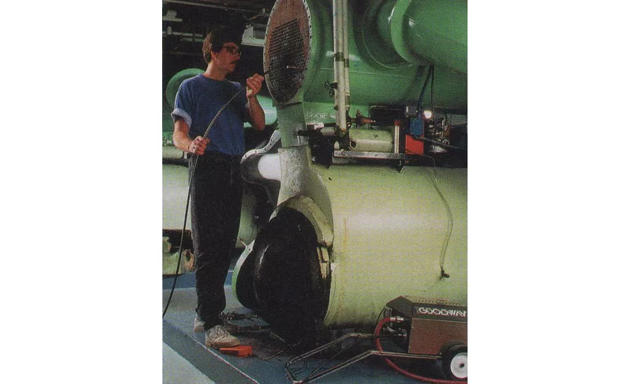
Bob said, “The head pressure should be about 210 psi on a design 95°F day, suppose the head pressure were to be 230 psi. The first thing I would do would be to feel of the liquid line and if the liquid line was extra warm or hot, I would highly suspect that the condenser is not taking the heat out of the refrigerant and transferring it into the water. So I would look then at the condenser water temperature inlet and outlet and see what these readings were. Suppose the entering water temperature were 85°F and the leaving water temperature 92°F, I would suspect again that the condenser is not transferring heat into the water going up to the cooling tower. Another more scientific method of proving the condenser tubes are fouled or dirty would be to check the approach at the condenser. With 92° leaving condenser water and a condensing temperature of 115°F (head pressure 243 psi) we would have an approach of 23°F. That would suggest the condenser tubes need to be cleaned, which would involve shutting the machine down and removing the water heads on the condenser and physically cleaning the tubes with brushes. (Figure 2).
You would also want to take a look at the refrigerant sight glass to make sure that it is full of liquid refrigerant with no bubbles in it. This would assure you that you have a solid column of liquid going to the expansion device”.
Tim then said, “I see, we have verified that there is proper water flow but the refrigerant heat is not moving into the water."
Bob said, “You’re getting the picture. It is always good to know from the data sheet what the equipment should be doing and if it isn’t doing that, look to see if you have a condenser problem or an the evaporator problem. A low charge for example would show up as a low suction pressure and bubbles in the refrigerant site glass."
Tim said, “I think that I have absorbed about all that I can for one session. Let’s get back to this another day with other problems with the chiller."
Publication date: 05/21/2018
Want more HVAC industry news and information? Join The NEWS on Facebook, Twitter, and LinkedIn today!
Looking for a reprint of this article?
From high-res PDFs to custom plaques, order your copy today!


