Operating and Troubleshooting Potential or Voltage Relays
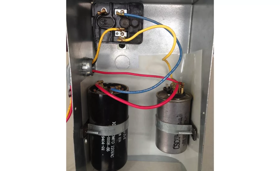
FIGURE 1: The potential relay consists of a very high resistance coil and a set of normally-closed contacts encased in a small plastic housing.
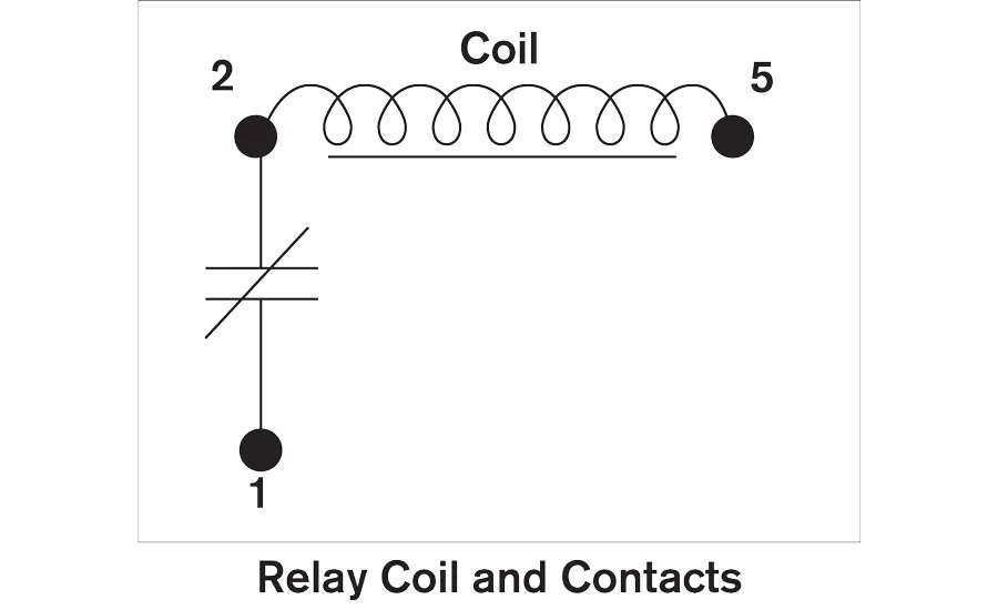
FIGURE 2: The relay coil is wired between contacts 2 and 5, while the normally closed contacts are wired between contacts 1 and 2.

FIGURE 2: The relay coil is wired between contacts 2 and 5, while the normally closed contacts are wired between contacts 1 and 2.
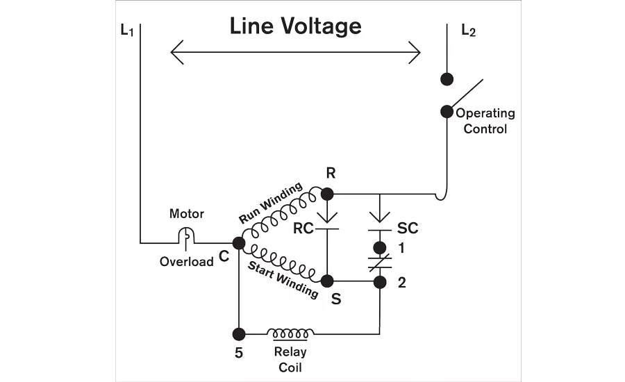
FIGURE 3: The run and start capacitors are wired in parallel to one another, yet both are in series with the start winding.
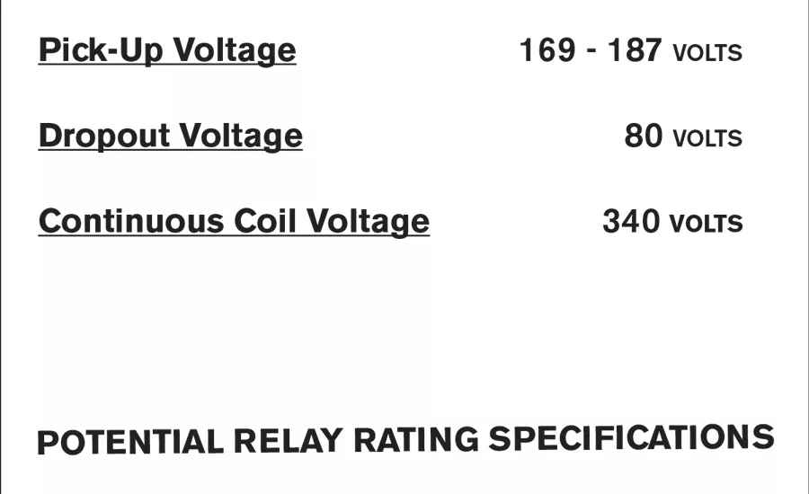
FIGURE 4: An example of a potential relay rating specification.
Potential relays are commonly found on many smaller, single-phase, capacitor-start, capacitor-run motors in the HVACR industry. Their function is to assist in starting the electric motor. Potential relays are sometimes referred to as voltage relays because they rely on the back-electromotive-force (BEMF) or voltage, which is generated by the motor for their operation.
Even though some manufacturers are incorporating solid state relays with their equipment, the potential relay is still probably the most popular small horsepower motor starting relay because of its ease of operation and troubleshooting. Because of the popularity and abundance of potential relays in the HVACR service field today, it is of utmost importance for service technicians to understand not only how this starting relay operates but also how to troubleshoot the components that make up the relay.
HOW POTENTIAL RELAYS OPERATE
The potential relay consists of a very high-resistance coil and a set of normally closed contacts. The coil and contacts are encased in a small plastic housing (see Figure 1). The relay coil is wired between contacts 2 and 5 while the normally closed contacts are wired between contacts 1 and 2 (see Figure 2). Other terminal designations on the relay are usually for connecting wires and acting as wire nuts. They often are used for incoming power, fans, or capacitor wire connections and are referred to as inactive or convenience terminals.
When power is delivered to a single-phase motor, both the run and start windings will be energized because the contacts between terminals 1 and 2 of the potential relay are normally closed. The motor’s rotor will now start to rotate or turn. In Figure 3, you will notice the run and start capacitors are wired in parallel to one another, yet both are in series with the start winding. The capacitance of capacitors wired in parallel will add, giving the motor more starting torque.
As the motor’s rotor turns faster and faster, trying to reach its synchronous speed, a generating effect is created from the rotor being a large metal mass rotating very close to the motor’s windings. Because the start winding is wound with a longer and thinner wire, more voltage or BEMF will be generated across it than across the run winding. BEMF can be measured with a voltmeter across the start winding while the motor is running. It is often higher than line voltage and can reach as high as 500V or more depending on the design and speed of the motor. The BEMF’s polarity opposes the line voltage’s polarity, so their magnitudes will not add. Because all motors generate different BEMF values, potential relays must be sized and chosen individually for each compressor.
Because the potential relay’s coil is wired in parallel to the start winding, this same voltage (BEMF) will occur across the relay coil. An electric circuit with voltage and current will be generated in the start winding and relay coil, causing the relay coil to energize and open the contacts between contacts 1 and 2.
This action occurs because the relay coil is wrapped around an iron core, which will magnetize once the coil is energized. This opening of contacts causes the start capacitor to be taken out of the circuit, and the motor will continue to run as a permanent split capacitance (PSC) motor.
Looking for quick answers on air conditioning, heating and refrigeration topics? Try Ask ACHR NEWS, our new smart AI search tool. Ask ACHR NEWS
Once the operating control opens and power is taken away from the motor, the motor speed will gradually decrease along with the BEMF generated. The relay coil will now de-energize, and the contacts between terminals 1 and 2 will return to their normally closed position as the motor comes to a stop.
RATINGS AND SPECIFICATIONS
Pick-up voltage — An example of a potential relay rating specification is listed in Figure 4. The pick-up voltage for a specific potential relay will be listed as a minimum and a maximum. The actual pick-up voltage must stay within its range for proper operation. The pick-up voltage is the BEMF voltage generated across the start winding by the motor’s rotor when it is up to about three-quarters speed.
If the pick-up voltage generated by BEMF is under the minimum, the contacts between terminals 1 and 2 will never open. The start capacitor will then stay in the circuit. This will cause high amp draws and can open motor-protective devices. However, if the pick-up voltage generated by BEMF is above the maximum, the relay coil stands a good chance to overheat and open circuit. Again, the contacts between 1 and 2 would stay closed, causing high amp draws if the relay coil opens circuit.
Continuous coil voltage — Potential relays also have a continuous voltage rating. This is the maximum BEMF the relay’s coil can tolerate continuously without overheating and opening circuit.
Drop-out voltage — Potential relays also have a drop-out voltage rating. The drop-out voltage is the BEMF voltage that must be generated across the relay coil to “hold” the contacts open once they have been picked-up (opened). Notice in Figure 4, it takes more BEMF (pick-up voltage) to pick up and open the contacts than it does to hold them open. Once the cycling control opens the circuit, the rotor will decrease in speed, thus generating less BEMF across the start winding and relay coil. As the BEMF drops below the dropout voltage, the contacts between 1 and 2 will return to their normally closed position and be ready for the next starting cycle.
Because of these three voltage rating specifications, service technicians must realize that potential relays must be sized to each individual compressor. Consult with a service manual, the compressor manufacturer, or a supply house for information on selecting the correct potential relay. Replacement relays can be cross-referenced for different manufacturers using convenient tables via the internet. Whenever possible, the model number on the old relay should be used when ordering a new relay.
TROUBLESHOOTING
A simple ohmmeter is all that is needed to troubleshoot a potential relay. After taking all connecting wires off the relay, measure the resistance across the 1 and 2 terminals. The resistance should read close to zero, since they are normally closed contacts. If the reader reads infinity, the contacts are stuck open, and the relay should be discarded and replaced. Open contacts will prevent the start capacitor from being in the circuit. This can lock the rotor and cause locked rotor amps under certain conditions, thus opening the compressor’s protection device. Short-cycling on the compressor’s protection devices can overheat and open a winding in time.
Often the relay contacts could be stuck or arced in the closed position. In this case, the start capacitor would never be taken out of the circuit, a rumbling sound would be heard, and high amp draws would open motor-protective devices. If the contacts are stuck in the closed position, the relay will have to be checked in the running mode, since the contacts between 1 and 2 are normally closed when not in operation.
Once the motor is up and running, use a voltmeter to measure the voltage across terminals 1 and 2. A voltage reading of zero volts would prove the contacts are not opening. Also, high amp draws in the start winding circuit is a tell-tale sign that the contacts have not opened.
After disconnecting all wires from the relay, ohm the coil between terminals 2 and 5 on the relay. Since this coil should have very high resistance, make sure you are using the proper scale on the ohmmeter (if it is not self-scaling). The R X 100 scale is a good one to use. The R X 1 scale can fool a technician into believing that there is an open coil because of the coil’s extremely high resistance. It is not uncommon to have the resistance read in the thousands of ohms. If the ohmmeter reads infinity on the R X 100 scale, the relay coil has opened. The relay should be discarded, and a new one installed. An open relay coil will prevent the contacts between 1 and 2 from opening because of no magnetism in the relay coil’s iron core. This, again, will cause high amp draws and a rumbling sound from the capacitor staying in the circuit too long.
Publication date: 3/5/2018
Looking for a reprint of this article?
From high-res PDFs to custom plaques, order your copy today!


