The Origin of Hydraulic Separation
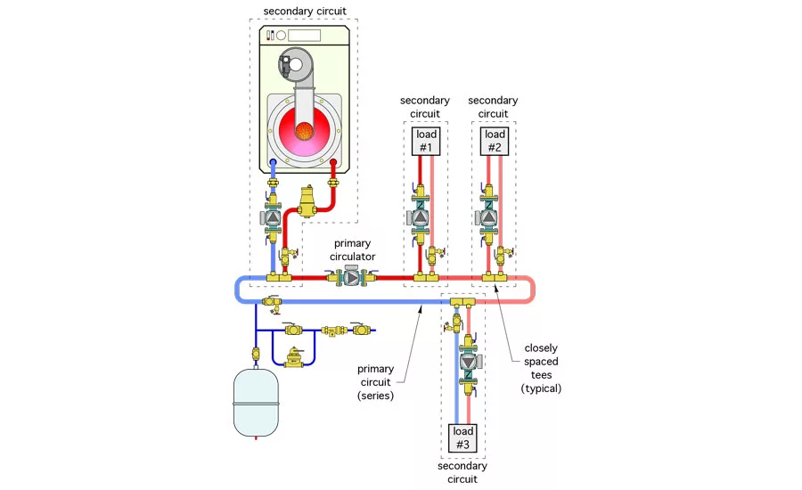
Figure 1.
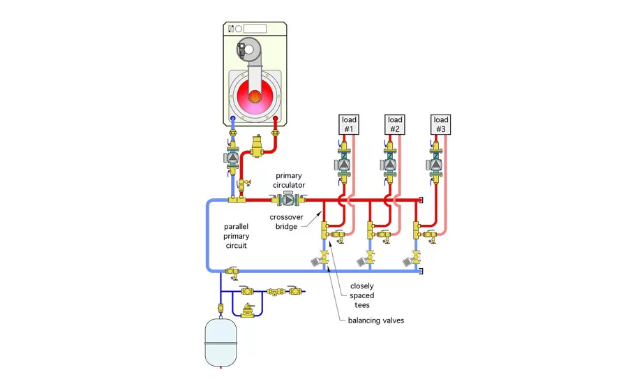
Figure 2.
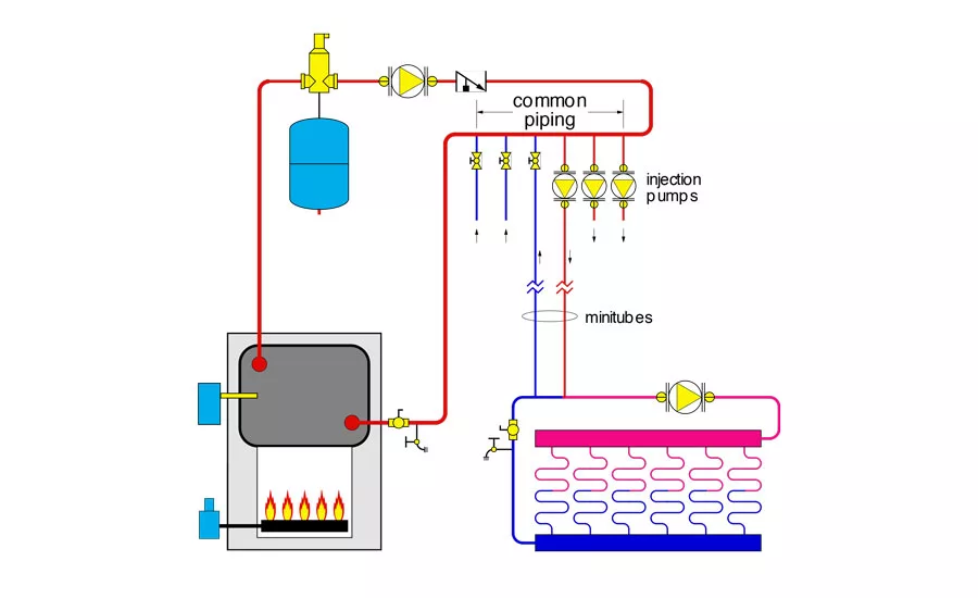
Figure 3.
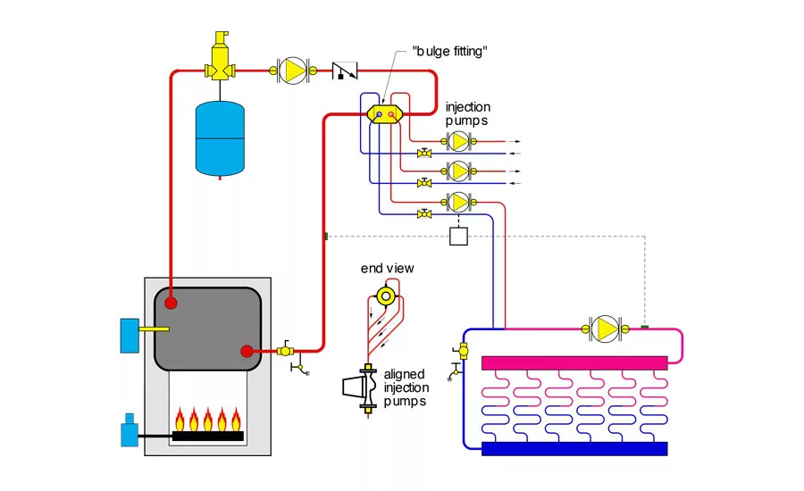
Figure 4.
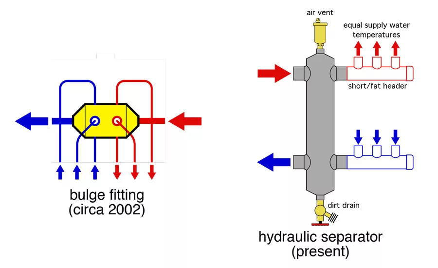
Figure 5.
I began writing about hydronics for Plumbing & Mechanical magazine in July of 1996. Back then, the hydronics market was expanding at a good pace and was largely driven by growing interest in radiant panel heating. The market was searching for piping and control techniques for multi-load/multi-temperature systems that could incorporate a range of loads, such as radiant panel heating, domestic water heating, higher-temperature heat emitters, snow melting, and pool heating. Imagine trying to properly supply all those loads using the very limited design approaches that defined residential hydronics in North America back in the 1980s.
One technique that steadily gained acceptance was primary/secondary piping using a series primary loop. An example of such a system is shown in Figure 1.
Although series primary/secondary systems can serve multiple loads, they operate with a temperature drop across each set of closely spaced tees that supply an active secondary circuit.
If all the secondary circuits are assumed to operate simultaneously and remain at design load conditions, it would be easy to calculate the temperatures and flows at all locations within the system and size the heat emitters accordingly.
Too bad such circumstances almost never exist in real applications. The constant variation in loads means water temperatures along the primary circuit could vary over a significant range. How do you properly size a heat emitter if you don’t know what the supply water temperature might be, depending on what other loads are active?
One way to eliminate this unpredictable temperature drop situation is to create a parallel primary circuit as shown in Figure 2.
This piping arrangement supplies each secondary circuit with the same water temperature but requires considerably more hardware and installation labor.
Looking for quick answers on air conditioning, heating and refrigeration topics? Try Ask ACHR NEWS, our new smart AI search tool. Ask ACHR NEWS
THE QUEST CONTINUED
Imagine yourself back in the early 1990s trying to create a multi-load/multi-temperature system while keeping all the required circulators within that system from interfering with each other and supplying the same water temperature to each load takeoff point. What other approaches could make this possible?
This is what makes hydronics technology so interesting. There’s a continuing challenge to accomplish design objectives using new approaches that are more elegant, less costly, or thermodynamically superior to current methods. Sometimes a new hardware device enters the market that makes this easy. Other times, it’s the realization that a different combination of existing hardware and controls provides a better solution.
The pursuit of achieving the benefits offered by a parallel primary loop system, but with less hardware, leads to some interesting ideas. One of them is shown in Figure 3, which originally appeared in my March 2002 Hydronics Workshop column. It shows a concept that was proposed to me by Tibor Kovacs, who, at the time, worked for IPEX.
This is a partial schematic for a three-zone mini-tube distribution system. Each of the three injection pumps operates at independently controlled variable speeds. They route hot water from the primary loop to the downstream tee of a pair of closely spaced tees at each manifold station. Mixing occurs at this tee. The speed of the injection pump determines the mix proportions at this tee and thus the blended water temperature supplied to the radiant panel circuits. Ideally, water at the same temperature is available to each of the three injection pumps.
Kovacs’ idea was to group all the tees that supplied hot water to secondary circuits and put them upstream of all the tees that let return flow back into the primary loop. His rationale was that this would provide the same water temperature to each secondary circuit without the complexity of a parallel primary loop. This would be true, provided the primary loop flow never reversed between the tees.
The fly in the ointment of this approach is that the accumulating piping length along these tees contributes to head loss and thus degrades hydraulic separation between the injection pumps. My hunch is that this arrangement would work in most situations, but it isn’t quite perfection.
I liked Kovacs’ idea but wanted to reduce that accumulating piping distance between the tees. This led to the idea of a “bulge fitting.” Figure 4 shows one possible way such a fitting could be incorporated into a primary loop that supplies three independently controlled variable-speed injection pumps.
The rationale behind the bulge fitting is that it places the supply point for each secondary circuit at the same dynamic pressure point in the system. All the returns from the secondaries also are grouped together and located just slightly downstream of the supplies. As long as flow continues to move from right to left through the bulge fitting, all the secondary supplies would be at the same temperature.
The increased diameter of the bulge fitting would slow the flow velocity and make the pressure drop between the supply points and return points almost zero. This would provide excellent hydraulic separation between all the injection pumps and between these pumps and the primary loop circulator.
Admittedly, the bulge fitting looks pretty ugly. Although the fluid mechanics associated with this fitting would work, the practicality of installing all those supply and return tubes in such proximity is not appealing. Since this article ran in 2002, I’ve yet to see any manufacturers produce a bulge fitting.
However, all is not lost. Guess what showed up in the North American hydronics market in 2002 that accomplishes the same thing as that bulge fitting and looks a lot better?
INTRODUCING THE HYDRAULIC SEPARATOR
The hydraulic separator slowly made its way from Europe into the North American market about 13 years ago. Hydraulic separators are now available in a wide variety of sizes from several North American suppliers. They are showing up in an ever-increasing number of hydronic heating and cooling systems.
Figure 5 shows a conceptual bulge fitting next to a modern hydraulic separator. Can you see the similarities in each approach?
The short/fat header at the upper right of the hydraulic separator provides equal supply water temperature to each load circuit. Also, it creates very little pressure drop along its length, which contributes to good hydraulic separation. Ditto for the return header at the lower right of the separator.
The wide “barrel” of the hydraulic separator slows the vertical flow velocity to the point where the dynamic pressure drop through the separator is almost zero.
Put the flow characteristics of these headers and barrel together and you achieve excellent hydraulic separation of all attached circulators.
Taking it a couple of steps further, the vertical orientation of the hydraulic separator combined with an internal coalescing media provides high-performance air separation. This eliminates the need for any other central air separator in the system.
The low-flow velocity zone at the bottom of the hydraulic separator allows dirt particles returning from the system to drop into the bottom “bowl” of the separator. Opening the valve at the bottom of the separator allows this dirt to be flushed out of the system.
The bulge fitting concept was a blurred vision of what would eventually become a well-accepted device (e.g., modern hydraulic separators). The bulge fitting concept was derived based on the same principles that apply to today’s hydraulic separators but lacked the ultimate functionality and ease-of-installation that modern hydraulic separators provide.
I suspect that a decade from now some of us will look back on today’s state-of-the-art hydronics technology with this thought: “Why didn’t we think of that 10 years ago?” Constant pursuit of improvement is the spice of life.
Publication date: 12/12/2016
Want more HVAC industry news and information? Join The NEWS on Facebook, Twitter, and LinkedIn today!
Looking for a reprint of this article?
From high-res PDFs to custom plaques, order your copy today!


