Selecting the Proper HVAC Fan System
Factors include static pressure, velocity, water gauge, and more
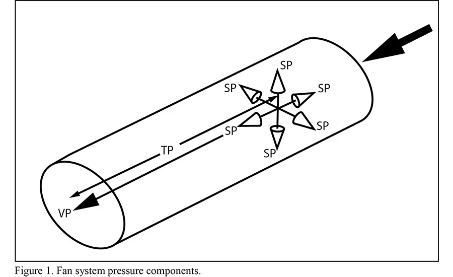
FIGURE 1: Fan system pressure components.
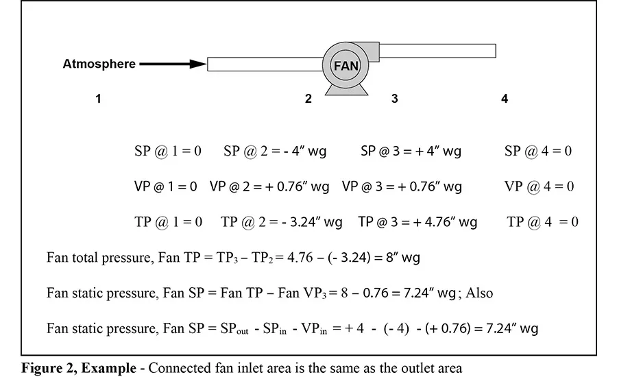
FIGURE 2: Connected fan inlet area is the same as the outlet area.
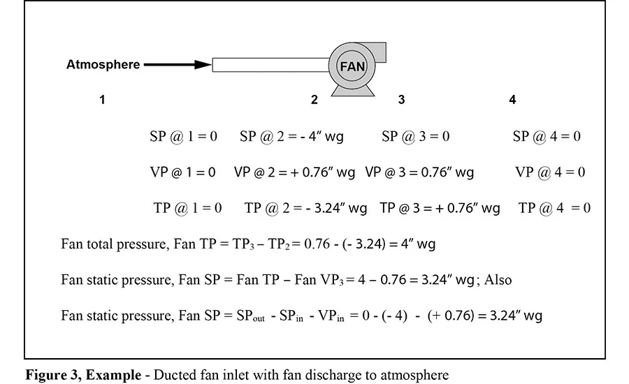
FIGURE 3: Ducted fan inlet with fan discharge to atmosphere.
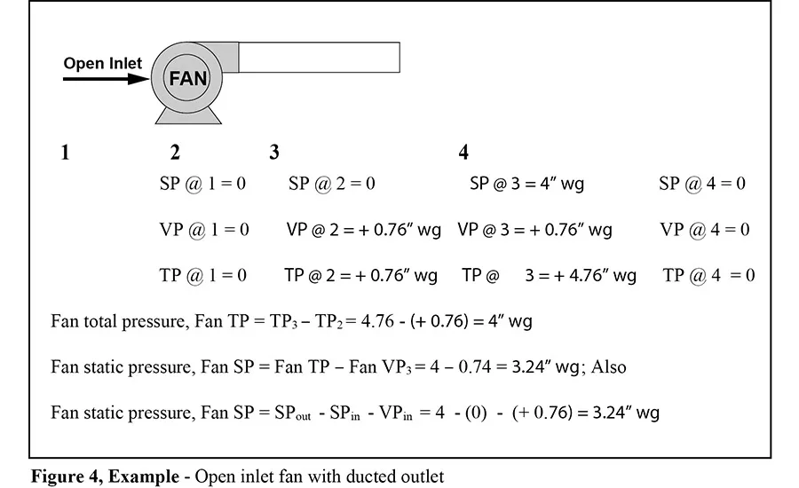
FIGURE 4: Open inlet fan with ducted outlet.
Fans and fan systems are significant energy consumers in many commercial applications and can be the greatest consumers in industrial applications. Concerned about being responsible for underperforming systems, designers tend to compensate for uncertainties in the design process by adding capacity to fans. Unfortunately, oversizing fan systems creates problems that increase expenses while potentially decreasing reliability.
INLET AIRSTREAM CONDITIONS
When selecting a fan, criteria include airstream characteristics, capacity, pressure, power, and efficiency.
Fan manufacturers’ published ratings for airflow, pressure, and power are based on standard laboratory conditions using standard cubic feet per minute (scfm) for airflow and 0.075 lb/ft3 for standard fan inlet airstream density. As such, the manufacturer’s published ratings can normally be used for fan selection and evaluation when the deviation between standard density and the actual site density at the fan inlet is less than 5 percent. This occurs when the following parameters are met at the fan inlet:
• The fan inlet temperature is between (+) 40°F and (+) 100°;
• The fan inlet static pressure is between (–) 12 in. water gauge (wg) and (+) 12 in wg;
• The fan inlet airstream moisture content is less than 0.02 pounds of water per pound of dry air or the dew point is less than 80°F; and
• The fan installation is between ± 1,000 feet elevation above sea level (asl).
In cases where one or more of the above parameters are not met, the inlet airstream density should be corrected to the actual conditions. This is normally referred to as non-standard air, with fan airflow noted as actual cubic feet per minute (acfm). Corrections for inlet airstream density are calculated by multiplying the standard density, airflow, pressure, and power by the density factor. The density factor (Df) is calculated as follows:
• Temperature (°F)
Dft = (530) / (460 + inlet temperature °F);
Looking for quick answers on air conditioning, heating and refrigeration topics? Try Ask ACHR NEWS, our new smart AI search tool. Ask ACHR NEWS
• Pressure (in wg)
Dfp = (407 in wg + inlet pressure, in wg) / 407 in wg;
• Moisture (lb. water/lb. dry air)
Dfm = (1 + ω) ÷ (1 + 1.607ω), where ω = lb. water / lb. dry air
• Elevation (feet above sea level)
Dfe = [1 – (6.73 x 10 –6) (z)]5.258 where z = elevation in feet.
density factor (Df) = (Dft) (Dfp) (Dfm) (Dfe )
FAN PERFORMANCE
If a fan is selected from the manufacturers’ standard catalogued ratings for an actual volumetric flowrate of 30,000 ft3/min (acfm), 15 in wg static pressure, 1,910 rpm, and 86 hp, but installed at the above conditions, then the fan operating performance would be:
• The actual volumetric capacity would be 30,000 ft3/min;
• The actual mass flow capacity would be 1,575 lbm/min (30,000 x 0.0525);
• The actual static pressure delivery would be 15 in wg x 0.70 = 10.5 in wg;
• The actual fan shaft power consumption would be 86 hp x 0.70 = 60.2 hp; and
• The actual inlet airstream density would be (0.70) (0.075 lb/ft3) = 0.0525 lb/ft3
FAN CAPACITY
Fan capacity can be stated either in terms of volumetric flow rate (ft3 /min) or mass flow rate in pound mass per minute (lbm/min). If a fan has a volumetric capacity of 30,000 ft3/min, then, at standard conditions and standard density of 0.075 lb/ft3, the mass delivery is then 30,000 ft3 /min x 0.075 lb/ft3 = 2,250 lbm/min.
Now, assume that the substance is air at non-standard conditions and has a density of 0.0525 lb/ft3. The mass delivery is now 30,000 ft3/min x 0.0525 lb./min3 = 1,575 lbm/min.
If the fan system must maintain a minimum mass flow rate of 2,250 lbm/min, then the required actual volumetric flow rate is 2,250 lb/min ÷ 0.0525 lb/ft3 = 42,857 ft3/min, and the fan should be selected on the volumetric basis of 42,857 actual ft3/min.
FAN PRESSURES
The most common pressure used in air-moving applications is static pressure. However, a basic understanding of all pressures is essential for the proper selection and operation of fans. These are total pressure (TP), velocity pressure (VP), static pressure (SP), fan static pressure (Fan SP), and fan total pressure (Fan TP).
The pressure components of total, static, and velocity pressure are shown in Figure 1. Total pressure is parallel to the direction of flow and is measured in the direction of flow. Velocity pressure is parallel to the direction of flow and can only be measured indirectly as the differential between total and static pressures. Static pressure is expressed equally in all directions and is measured perpendicular to the direction of flow.
TOTAL PRESSURE
Total pressure represents the total energy at the point of measurement: TP = VP + SP.
Total Pressure can be either positive or negative, depending on the measurement location.
VELOCITY PRESSURE
Velocity Pressure is the kinetic energy in the direction of flow that causes a fluid at rest to flow.
• VP = TP - SP;
• VP = (V ÷ 4005)2 (Df); and
• VP is always positive, independent of its measurement location.
STATIC PRESSURE
Static Pressure is the potential energy exerted in all directions by the fluid.
• SP = TP - VP;
• SP is mutually convertible with VP; and
• Static pressure can be either positive or negative, depending on the measurement location.
FAN TOTAL PRESSURE VS. TOTAL PRESSURE
While TP is the difference in VP and SP, fan total pressure is the increase in total pressure through or across the fan and represents the total work delivered by the fan. Fan total pressure, as defined by Air Movement and Control Association Intl. Inc. (AMCA) standards, is not normally used for fan-rating purposes. In some cases, specialized fans may be rated based on fan total pressure; however, an understanding of fan total pressure is important for a proper understanding when measuring fans and fan systems. Fan total pressure is expressed as:
• Fan TP = TPfan outlet - TPfan inlet; and then
• Fan TP = (SPoutlet + VPoutlet) - (SPinlet + VPinlet).
When the velocity pressures at the fan inlet and the fan outlet are the same, the velocity pressures cancel out and the Fan TP calculation is simplified to:
• Fan TP = (SPoutlet) - (SPinlet)
If the fan inlet and outlet areas are not identical, then this simplification cannot be used. Since, in this case, the fan TP is simply the sum of the static pressures on the inlet and outlet sides of the fan, when the fan is specified on the basis of summing the inlet and outlet static pressures (static pressure rise across the fan), the fan rating is actually on the total pressure basis.
Figures 2, 3, and 4 show fan calculations for various system conditions and configurations.
FAN STATIC PRESSURE VS. STATIC PRESSURE
While SP is the difference in TP and VP, Fan SP is defined as the Fan TP minus the fan velocity pressure at the fan outlet and represents the change in atmospheric pressure at the fan inlet.
Fan SP, as defined by AMCA, is the basis for most fan ratings. In some cases, specialized fans may be rated based on Fan TP. Since the Fan TP equals the difference in the total pressure across the fan, then Fan SP is expressed as:
• Fan SP = Fan TP - Fan VPoutlet;
• Fan SP = (TP Fanoutlet - TP Faninlet) - VP Fanoutlet; and then
• Fan SP = (SPoutlet + VPoutlet) - (SPinlet + VPinlet) - VPoutlet.
Since the VPoutlet’s are identical and cancel out, then Fan SP = SPoutlet - SPinlet - VPinlet.
However, it’s not uncommon to find that the static pressure used for fan selection is calculated as SPoutlet - SPinlet. In this case, the fan is often oversized by the VPinlet energy component and can result in excessive energy consumption.
And, when the static pressure used for fan sizing is calculated in this manner, the fan cannot perform exactly on the fan curve, since the ratings basis between the fan manufacturer and the fan user differs by the velocity pressure component at the fan inlet. Figures 3 and 4 present some examples of how to calculate the fan pressures at various fan configurations.
FAN POWER
Fan horsepower is normally referred to as brake horsepower (BHP). However, we can gain a clearer understanding of fan horsepower if we look at power in BHP, operating horsepower (OHP), and air horsepower (AHP).
BHP
BHP, which is sometimes called chart horsepower (CHP), is the power required at the fan shaft to drive the fan. It normally includes bearing drag, but does not include any other losses, such as v-belt drive loss or motor or variable fan drive (VFD) inefficiencies.
The fan horsepower stated by the fan manufacturer from its published charts or selection programs represents only the power required to drive the fan shaft and only at standard airstream density conditions of 0.075 lb/ft3.
OHP
OHP is the horsepower consumed by the fan and its driver during operation. It includes the energy required by the fan shaft (BHP), the energy required by the driver, and the effects of any changes in inlet airstream density from standard conditions.
OHP = (BHP x density factor) + (drive loss).
FOR EXAMPLE
If a fan is selected for 30,000 ft3/min, 15 in wg sp, 1,910 rpm, and 86 BHP based on the manufacturers’ catalog ratings but installed at the conditions noted in the example under the “Fan Performance” subhead, then the fan operating performance would be:
• Density factor = Df = (0.83) (0.96) (0.98) (0.90) = 0.70;
• Calculated airstream density = 0.0525 lbm/m3;
• The actual volumetric capacity would be 30,000 ft3/min;
• The actual mass flow capacity would be 1,575 lbm/min;
• The actual static pressure delivery would be 15 in wg x 0.70 = 10.5 in wg;
• The actual fan shaft power consumption would be 86 bhp x 0.70 = 60.2 hp;
• The v-belt drive loss from AMCA would be 4 percent of motor output power; and
• The OHP = (BHP x density factor) + (drive loss): = (86 bhp x 0.70) + (4 percent x 60.2) = (60.2 hp) + (2.4 hp) = 62.6 OHP
In summary, operating horsepower allows for changes in airstream composition and the energy losses required to drive the fan, and both the OHP and BHP should be considered in motor selection.
AHP
AHP is the energy added to the airstream per unit of time and is considered to be the actual horsepower output of the fan.
• AHP = (flow rate x total pressure) / 6,362;
• Using 30,000 actual ft3/m and 16 in wg actual total pressure; thus
• AHP = (30,000 x 16) / 6,362 = 75.5 hp added to the airstream.
It is often helpful to calculate the AHP output of the fan in order to better understand the construction requirements of the fan system and the energy available within the system.
FAN EFFICIENCY
Fan efficiency is the ratio of the horsepower output of the fan to the horsepower input to the fan. From the preceding section on fan power, the horsepower output is defined as the AHP, and the horsepower input is defined as the BHP.
• Fan efficiency = power output ÷ power input; and
• Fan efficiency = AHP ÷ BHP.
Fan efficiency can be evaluated either on the basis of total pressure or static pressure. As discussed previously, TP and SP are summarized as follows:
When the total pressure basis is used, the fan efficiency is defined as total (mechanical) efficiency, and both the static and velocity pressure components are considered.
When the SP basis is used, the fan efficiency is defined as static efficiency, and only the SP component is considered. Total and static efficiency are calculated as follows:
• Total Efficiency = (total pressure, in wg x flow, ft3/m) ÷ (6,362 x BHP) x 100 percent; and
• Static Efficiency = (static pressure, in. wg x flow, ft.3/m) ÷ (6,362 x BHP) x 100 percent.
Since total efficiency is based on the fluid in motion while static efficiency is based on the fluid at rest, fan evaluation and selection based total efficiency normally represents the truest performance measure of the fan’s capability.
SUMMARY
Correctly understanding and calculating fan static pressure will prevent unintended over-design and system horsepower consumption. The fan motor should always be selected based on operating horsepower, as selection based on BHP horsepower can result in unintentionally selecting the incorrect motor.
When changes to an existing system need to be made, properly calculating the new system requirements based on the characteristics of each type of system component (ducting, air pollution control equipment, after-filter, etc.) will result in the optimum design and prevent unintended over-design.
Understanding fan total and static efficiencies will aid the user in identifying and selecting the best fan for the application, and thorough consideration of all the fan and system parameters will aid the user in arriving at the most energy-efficient design.
Information courtesy of Khalil Kairouz, senior project manager, Carollo Engineers; Dale Price, president of M&P Air; and Albert Rau, CEO of UDECM. Contact them at kkairouz@carollo.com, dprice@mpair.com, and arau@udecm.com.
Publication date: 4/18/2016
Want more HVAC industry news and information? Join The NEWS on Facebook, Twitter, and LinkedIn today!
Looking for a reprint of this article?
From high-res PDFs to custom plaques, order your copy today!


