Modern VFDs Optimize Motor Operation

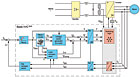
Schematic diagram of a modern drive.
It was VFDs that made speed control of the inexpensive, robust, and low-maintenance three-phase induction motor standard in many applications. The availability of simple electronic speed control made possible improved product quality and better utilization of production lines.
Over the years, advances in solid-state transistors, miniaturization of components, and the advent of the microprocessor have contributed to the evolution of more compact VFDs with powerful control features, offering sophisticated motor control and high reliability.
MODERN VFD STRUCTURE
The speed of an AC induction motor is directly related to the frequency of its electrical supply and the number of electrical poles within the motor. On a 60-Hz main supply, a four-pole motor will rotate at a speed of 1,800 rpm unless some slight slip is caused by the load.By controlling the motor with a VFD, the motor will run at a speed proportional to the input frequency provided by the drive. However, in order to generate full shaft torque, the motor input voltage must also be regulated in proportion to the frequency. For example, for a motor rated at 460V/60Hz to be run at half speed, it should be supplied at 230V/30Hz. This type of VFD, where the V/Hz ratio is maintained, is known as a voltage source inverter.
Earlier types, particularly in the high-power area, maintained the current/frequency (i/f) ratio constant and were known as current source inverters. These have largely been superseded and now, even in large-megawatt power VFDs, voltage source is state of the art.
In the VFD, the incoming AC line is first rectified to DC, which is then smoothed by an inductor/capacitor circuit and maintained at a constant level. Early VFDs affected output voltage control through controlled rectification and the DC bus was variable, but the VFD output waveform was somewhat crude.
Since the early 1990s, digital control of fast-output transistors in the power inverter section has been delivering a smooth, controlled variable voltage and variable-frequency supply to the motor, enabling smooth speed control over a wide speed range.
Many large factories use hundreds of VFDs for smooth control of their production lines.
CONSTANT-AMPLITUDE DC VOLTAGE
The intermediate circuit smoothes the DC voltage and compensates for load surges, such as during start-up or during sudden load changes, and acts as a buffer circuit for the energy the VFD supplies the motor. Modern drives use a DC voltage of constant amplitude. For energy storage, they typically use electrolytic capacitors that also smooth the pulsating DC voltage.In practice, under no-load conditions, the VFD DC link voltage is typically about √2 x mains voltage. The DC link voltage drops under load but in motor regenerative operation, such as during fast deceleration of high-inertia loads, the motor feeds energy back into the intermediate circuit and the DC link voltage increases. If the voltage attempts to exceed the intermediate critical value, the VFD will either back off the deceleration ramp, or cut the supply to the motor to prevent damage.
In contrast to a purely resistive load, the capacitive smoothing of the DC link results in a non-sinusoidal voltage. This creates network effects or harmonics. In a three-phase supply, these harmonics range in frequency up to about 2 kHz. As a countermeasure, inductive chokes are fitted in series in the intermediate circuit to limit these harmonics. Another advantage of chokes in the DC link is that they smooth the charging of the capacitor and thereby extend its life.
To minimize system disturbance, some manufacturers reduce the capacitance of the intermediate circuit, or even eliminate the DC link capacitors entirely. This does not completely eliminate the line-side disturbances, but moves them to other frequency ranges (up to 10 kHz). This, however, causes problems through the reduced or lack of smoothing of the DC link voltage. Thus, only a reduced motor voltage is available at the drive output, resulting in higher currents for full-load motor operation at the same duty point, with increased motor heating.

Built-in chokes reduce the line harmonic distortion and protect the dc link capacitors.
POWER INVERTER - OPTIMAL FREQUENCY CONTROL
The inverter section is the final stage in the VFD before the motor, and it is within the inverter section that the rectified DC is switched to provide an AC supply controlling both the voltage and frequency to the motor. Equally, the drive must also ensure optimum supply conditions throughout the operating range by adjusting the output voltage and frequency to meet load conditions. Controlling the ratio of output voltage to output frequency (v/f ratio) ensures optimal magnetization of the motor at all times.The main components of the VFD are typically six insulated gate bi-polar transistors (IGBTs), arranged in pairs on three branches similar to the structure of the rectifier. These fast-operating devices switch positive and negative voltage pulses of variable width to generate a variable frequency and voltage supply.
Early VFDs used a simpler alternating method with single voltage pulses of varying amplitude, but this design required a controlled rectifier front end, generating a variable DC link, and it provided only the most basic motor speed control over a limited range.

Output voltage of sine-wave pulse-width modulation inverter.
The quality of the output waveform determines the quality of motor control and differentiates one manufacturer’s VFD from another’s. The greater the degree of motor control required, the greater the sophistication and design of the control processors and software required. Simple control will limit the performance and also increase negative aspects, such as motor heating.
Generating optimum performance requires a high degree of control complexity. Methods vary but basically break down into two groups: voltage vector control, where the voltages in the motor stator are monitored, calculated, and thus controlled; and current vector, where the rotor current is monitored and controlled.
Simplified diagram of VVC+ Control.
CONTROL BOARD ENSURES RELIABILITY
The control circuit provides the intelligence to the VFD and has the following main tasks: control of the switching of the output semiconductors; data exchange between the drive and external controls; monitoring of the drive and displaying messages and relevant data; and managing protective functions for the drive and motor.With the advent of more powerful digital processors, drives are incorporating increased control functions such as integrated power management, multiple PID controllers, and programmable logic functionality. The primary function of the control circuit, however, remains the control of motor speed and torque. The control philosophy provides for fast, accurate control of the amplitude and frequency of the voltage vector, to ensure that the motor’s magnetizing flux is optimized under all running conditions.
Publication date: 04/05/2010
Looking for a reprint of this article?
From high-res PDFs to custom plaques, order your copy today!


