Causes of high condensing temperatures include dirty condenser coils, restricted condenser airflow (fan out), air in the system, an overcharge of refrigerant, and/or high ambient temperature.
Causes of low suction pressure include iced evaporator coils, restricted evaporator airflow (fan out), an undercharge of refrigerant, dirty evaporator coil, end of the running cycle, thermostat or LPC set wrong, and/or low evaporator heat load.
However, one of the most elusive causes of compressor motor overheating and failure is voltage unbalance. This article will address voltage unbalance in three-phase compressor motors.
Voltage Unbalance
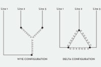
Voltage unbalance can be found with a voltmeter by measuring between phases on the compressor's motor terminals, at the disconnect, or at the contactor or starter terminals. Some of the more common configurations in three-phase motor windings are the Wye and Delta configurations.By measuring voltages from Line 1 to Line 2, Line 2 to Line 3, and Line 3 to Line 1, and performing a few simple calculations, a technician can determine if there is a voltage unbalance problem. Voltage unbalance exceeding more than 2 percent in three-phase systems can cause current unbalance among the windings. These, in turn, can cause an increase in winding temperature and an overheating problem that can be harmful to the motor.
The three-phase motor terminals are connected directly to the motor windings. The motor windings are housed in the motor barrel. The motor barrel houses, protects, and cools the motor windings as superheated refrigerant gas flows through it.
Measurement Examples
Step 1.Measure line voltages between phases:Line 1 to Line 2 = 216 V.
Line 2 to Line 3 = 223 V.
Line 1 to Line 3 = 225 V.
Step 2. Find the average of the three line voltage readings:
216 V + 223 V + 225 V = 664 V.
664 V ÷ 3 = 221.33 V average.
Step 3. Find the unbalance for each phase by figuring the difference between each phase voltage (step 1) and the average voltage (step 2). Make sure the subtraction comes out to be a positive number:
Line 1 to Line 2 = 221.33 – 216 = 5.33 V.
Line 2 to Line 3 = 223 – 221.33 = 1.67 V.
Line 1 to Line 3 = 225 – 221.33 = 3.67 V.
Step 4. Take the largest unbalance in step 3 (in this case, 5.33 V) and divide it by the average volts found in Step 2. Multiply by 100 to put it into a percentage form:
Percent unbalance = (largest unbalance divided by average volts) x 100.
Percent unbalance = (5.33 ÷ 221.33) x 100.
Percent unbalance = 2.4 percent.
As mentioned earlier, a voltage unbalance exceeding more than 2 percent in a three-phase system can cause excessive current unbalance among the windings. This article's sample voltage unbalance (2.4 percent) exceeds the 2 percent limit and can cause an increase in winding temperature that is detrimental to the motor.
The equation that follows shows how voltage unbalance affects temperature rise in the motor:
Percent temperature rise = 2 x (percent voltage unbalance)2.
Percent temperature rise = 2 x (2.4)2.
Percent temperature rise = 11.52 percent.
As you can see, the 2.4 percent voltage unbalance caused an 11.52 percent increase in winding temperature over the motor's normal operating winding temperature.
John Tomczyk is a professor of HVACR at Ferris State University, Big Rapids, Mich. He can be reached by e-mail at tomczykj@tucker-usa.com.
Publication date: 04/04/2005


