The Importance of VRF System Certification
These systems are best served by technicians familiar with systems’ best practices

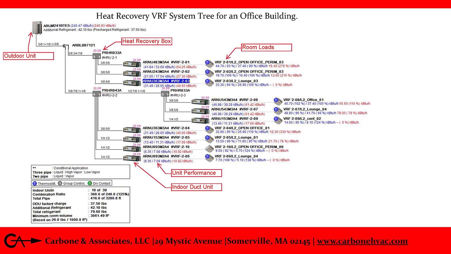
It's important to select the optimum fan coil unit system for multiple occupant comfort zones. LG VRF diagram provided by Carbone & Associates LLC
This article first appeared in Engineered Systems. View the original post in its entirety here.
Variable refrigerant flow (VRF) systems were first introduced to the HVAC community in Japan in 1980 as a highly efficient heating and cooling option in multi-zone comfort applications. It took the U.S. about 25 years to first embrace VRF concepts. Before VRF, engineers opted for the more traditional and less energy-efficient direct expansion (DX) cooling and heat pump (C&HP) options or costlier air- and water-cooled chilled water systems for multiple occupant comfort zones using either 2- or 4-pipe fan coil units.
DX systems were limited in their capabilities and continue to have limitations today. Still, DX systems remain popular because of their first-cost benefit; ability to adapt to C&HP pay-as-you-go phased construction; and their simplistic design, installation, and operation. For HVAC engineers, knowledge of refrigeration cycle theory comes into play with DX design, and, quite often, contractors will bypass a design engineer and go directly to the manufacturer for equipment size and selection options and features. Unless the consultant is in the process refrigeration industry, the design engineer will not need to refer to his or her refrigeration design manual for the majority of HVAC comfort-cooling commercial, institutional, and industrial applications. The same can be said for installing refrigeration technicians trained to install, pressure test, and startup DX systems because refrigeration theory and the associated automatic temperature controls (ATC) for these types of HVAC systems are not complicated. In fact, some HVAC equipment, such as rooftop air-handling units, packaged terminal air conditioner (PTAC) units, etc., comes completely packaged.
VRF system applications are rapidly growing in the building industry. Over the last 10-15 years, this growth has brought with it the need for HVAC design engineers to revisit refrigeration theory and be proficient with its design application. Oftentimes, consultants have not invested sufficient time to become proficient in engineering a VRF system and instead have relied on the equipment manufacturer’s sales engineer representative for design support. Working with sales engineer representatives is not unusual, as all HVAC equipment manufacturers — or their own in-house engineering departments — have always been available to provide technical support to design engineers. With VRF system applications, far more knowledge of refrigeration system design, startup, and operation are needed for both the design engineers and refrigeration technicians who will eventually be installing this equipment. As a result, VRF equipment manufacturers often require installing refrigeration technicians to become certified, and installation must be completed by a certified technician if a client is to receive the manufacturer’s extended warranty.
ASHRAE Handbooks on Refrigeration
ASHRAE offers the industry four handbooks that are update every four years: 2017-Fundamentals, 2018-Refrigeration, 2019-HVAC Applications, and 2020-HVAC Systems and Equipment. These handbooks provide the foundation to the HVAC building industry with additional ASHRAE guidelines and standards along with other technical books, guidelines, standards, etc., including Air-Conditioning, Heating, Refrigeration Institute (AHRI) Standard 545 (2017), “Performance Rating of Modulating Positive Displacement Refrigeration Compressors.”
Before the surge of HVAC applications, design engineers seldom needed to refer to 2018 ASHRAE Handbook-Refrigeration. As VRF systems became more popular, more engineers turned to ASHRAE Handbook - HVAC Systems and Equipment, Chapter 18, “Variable Refrigerant Flow.” Unlike the engineering of a closed looped water system (chilled water or hot water) with varying positive pressure and variable water flow, refrigeration system pipe sizing depends on where the refrigerant is within the pipe distribution. At one point, the refrigerant will be a liquid, and at another point, it will be a gas. This system will also be under a positive pressure and then transition to a suction/vacuum pressure. In addition, the refrigerant flow will vary throughout the entire piping network, requiring special attention to oil management within the pipe distribution with a focus on consistent oil flow throughout the system.
The design engineer needs to take into account system safety and refer to ANSI/ASHRAE Standard 15-2019, “Safety Standards for Refrigeration Systems”, and ASME/ASHRAE Standard 34-2019, “Designation and Classification of Refrigerants.” While some may express their concerns with the use of refrigeration because of these safety standards and environmental issues, it is important to note that all heating and cooling mediums/agents have safety and environmental concerns that design engineers must take into account. Whether it’s an oil heating spill, natural gas leak, or electrical shock from the electrical power distribution, all come with codes and/or guidelines and standards directed to each application’s design, equipment startup, operation, maintenance, and disposal — and, all have an impact on the environment.
Looking for quick answers on air conditioning, heating and refrigeration topics? Try Ask ACHR NEWS, our new smart AI search tool. Ask ACHR NEWS
2018 ASHRAE Handbook-Refrigeration, Chapter 1, provides design engineers with piping principles, oil management in refrigerant lines, etc., along with the ATC sequence of operation for startup/shutdown and day and seasonal system management. This ASHRAE Handbook also provides design engineers and refrigeration technicians to research “Systems & Practice,” Chapters 1-9, and “Components & Equipment,” Chapters 10-18, while 2017 ASHRAE Handbook-Fundamentals, Chapter 29, “Refrigerants,” and Chapter 30, “Thermophysical Properties of Refrigerants,” provide a comprehensive understanding of refrigeration. Collectively, both handbooks, with their essential technical data, form the basis for designing, installing, startup, and operation of VRF systems in the HVAC industry.
Designing for Multiple Occupant Comfort Zones
When it comes to engineering a few to several occupant comfort zones, the ASHRAE Handbooks offer introductions to a diverse menu of HVAC systems. Design engineer should start with 2020 HVAC Systems and Equipment Handbook, Chapter 1, for system analysis and selection as the first step when deciding on the optimal system for the project. When selecting VRF as the optimal application, this decision will often be based on the analysis and selection of a VRF system (Figure 1) with its fan coil units (FCUs) versus a 2- or 4-pipe FCU system because of its lower first cost followed by its energy-efficient performance. This analysis and selection process will most likely not include input from experienced refrigeration technicians, but, eventually, a technician will need to be informed as to the methodical steps that contributed to the designer’s final selection. In the construction phase, this refrigeration technician, along with other contractors on the job, will be responsible for the installation, startup, testing, adjusting, and often commissioning of the FCU system with the intent that the contract document’s requirements as well as the design engineer’s original VRF system performance goals are achieved.
Both types of systems will require outdoor air as well as recirculated room air at the VRF or chilled water system’s FCUs. This outdoor air can be provided by a number of sources. For FCU applications, the preferred ventilation method is a dedicated outdoor air system (DOAS) with an energy recovery heat exchanger to reclaim the building’s exhaust air energy. FCUs should be engineered to remain on during occupancy and not cycle off when the thermostat’s set point is satisfied. The cycling on and off of FCU supply air, for most applications, e.g., classrooms, is not allowed by state code, and the technician setting up the control sequence of operation should be trained to recognize this often overlooked requirement.
Click diagram to enlarge
With VRF system applications, far more knowledge of refrigeration system design, startup, and operation are needed for both the design engineers and refrigeration technicians who will eventually be installing this equipment. Pictured here is a heat recovery VRF system tree diagram.
VRF System Versus a Traditional DX System
Traditional DX systems for comfort cooling came on the market in the early 1950s with the introduction of the packaged terminal air conditioner (PTAC) through-the-wall unit. This has been the mainstay for DX technology until the introduction of VRF systems in 1980 and their eventual arrival in America 25 years later. This new, more energy efficient, and more versatile DX concept has not only displaced the more traditional air conditioner for residential and commercial applications, it has very successfully challenged chilled water supply/hot water supply (CHWS/HWS) FCU applications, especially in first cost and quite often in energy efficiency.
The sophistication of VRF equipment and systems eventually led to special refrigeration technician certification requirements. Traditional DX installations are very straightforward for several reasons. First, traditional DX systems often consist of a compressor-condenser unit located outside of the building. This unit most likely will serve a single DX cooling coil. The pipe distribution route is often very simple and, as a result, refrigeration technicians may opt to use pre-charged refrigerant lines, eliminating field fabrication/soldering of fittings and pipe.
Traditional DX systems can be very limiting in the sequence of operation with single-stage, on-off, automatic controls or two-stage, high-low controls. Even the more sophisticated DX system applications that use hot-gas bypass still have a relatively easy automatic controls sequence of operation. All of this lends itself to a less difficult refrigeration piping installation; therefore, traditional DX systems do not usually get commissioned. DX installations are more complex when the technician has to field-fabricate and install the entire refrigeration installation. Here is where a DX equipment manufacturer’s sales engineer will most likely engineer the entire pipe distribution system for the technician, taking in the number of stages of control, length of pipe, the location above or below the compressor/condenser to the evaporator coil, and oil management within the refrigerant. That said, most installations will remain relatively simple, will not be commissioned, and will be completed without a requirement that the refrigeration technician be certified to install the specific manufacturer’s equipment to satisfy any warranty criteria.
VRF systems include a single compressor-condenser module, with each serving up to 20 FCUs, making the refrigerant flow variable rather than at high-low-off stages. This more diversified cooling-only, heat pump cooling or heating, or heat recovery simultaneous cooling and heating (Figure 2) application can be perceived as a hybrid DX system blending traditional refrigerant design engineering with CHWS/HWS design engineering because of its variable refrigerant flows and FCUs servicing numerous occupant comfort zones. With this more efficient, cost-effective cooling and heating system comes more concern to require commissioning for VRF systems. Similar to CHWS/HWS systems that require more than just pressure testing, the water pipe distribution CHWS/HWS systems also require a certified testing, adjusting, and balancing (TAB) technician to adjust flows to each FCU. VRF systems don’t require a TAB technician, but they do require more thorough installation compliance and startup when compared to other DX systems. Once completed, both the water FCUs and the VRF FCUs should be third-party commissioned to ensure design intent.
VRF System Certification
As this article has demonstrated, VRF systems are far more sophisticated with far more equipment and material parts than traditional DX systems, and, yet, the installing and startup of this complex refrigeration system is done by one individual: the refrigeration technician. No additional pipe insulation subcontractors, TAB technicians, or equipment manufacturer startup technicians are required. Refrigeration technicians will be required to perform all this work, possibly with the assistance of an apprentice or additional refrigerant technician(s), depending on the number of compressor/condenser units, FCUs, and condensate pumps.
To help with the certification process, manufacturers have strategically located refrigeration certification classrooms with hands-on training in certain parts of the country where technicians will attend one- or two-day sessions before receiving their certificate of VRF system education.
Interested technicians should be licensed refrigeration technicians before attending these classes, but others, such as design engineers, are welcome to attend and learn (Figure 4). The first goal for training is to introduce technicians to the sophistication of VRF versus conventional DX. The second goal is to train these technicians on installing refrigerant pipe distribution based on variable flow followed by education regarding training and troubleshooting startup. The ultimate goal is for the client who will own the VRF system(s) to be entitled to a 10-year manufacturer’s warranty on the equipment and to know the entire process was furnished and installed in accordance with this manufacturer’s requirements. Without a certified technician managing the installation of the system, completing the required startup checklist, and fulfilling the required pre-commissioning checklist, the warranty will be voided.
To break out the training curriculum, the following will be addressed by a prequalified instructor:
- Safety;
- Introduction to the equipment, including the outdoor variable-speed compressors and condensers, indoor FCUs, condensate pumps, and DOAS units;
- Introduction to parts and materials specifically associated with this equipment, the system configuration, and the application (cooling-only, heat pump cooling or heating, and heat recovery simultaneous cooling and heating);
- Discussion covering refrigerant and condensate piping;
- Discussion covering controls — pre-wired in the factory, field wired, and BACnet/internet interface;
- Hands-on training in a refrigeration training lab covering installation of the equipment, parts, and materials; and
- Completed startup sheet, including functional performance test (FPT) commissioning using an equipment manufacturer’s checklist.
At the start of the training lab education, the first topic of discussion will be safety, which, for the most part, will be a refresher course for the experienced technicians and other attendees but always worth reiterating. Next, the equipment discussion in this certification class will be an explanation of the air- and water-cooled condensing unit(s) with their variable refrigerant compressors and how these outdoor units are safely installed, secured, and piped. Students learn how these units start up, operate, and how to troubleshoot them through hands-on classes. The equipment training also discusses how indoor units are diversely engineered for a variety of applications, defines how to accommodate the associated condensate, and, when needed, a condensate pump’s set criteria
Both VRF systems and CHWS/HWS FCUs need to work in sync with an outdoor air ventilation source when serving occupied spaces. The training center educator will provide an introduction to DOAS while also providing education on what students need to know pertaining to the automatic control of a VRF system and how to integrate a DOAS unit.
The class introduces VRF parts and materials playing an important role into the installation and performance of these VRF systems; discusses the distance between the outdoor condensing unit and indoor FCUs; examines pipe sizes, whether it is a 2-pipe system or a heat recovery 3-pipe system; and vertical rise and/or drops between the outdoor unit and indoor unit(s). Integral in this discussion will be oil management within the piping systems as well as evacuation and pressure testing per industry standard guidelines.
The certification class draws upon the Copper Development Association manual, “The Copper Tube Handbook,” for selecting the engineered solution for the design addressing bending, joining, soldering, brazed joints, flared joints, and other joining methods.
Summary
From this class, technicians will be officially certified to complete the work and, in turn, clients will receive the manufacturer’s 10-year warranty at the completion of each project. Unlike the traditional, more simplistic DX systems, VRF systems are far more sophisticated, and the success of the project is dependent on a refrigeration technician completing the installation, startup, and pre-commissioning per the manufacturer’s best practices. One could say the responsibility lies with the design, but the refrigeration technician will have the majority of the responsibility to “get it right.” True, the setting up of the automatic controls to the engineer’s designed sequence of operation is essential to a project’s success but, without following the proper refrigeration fundamentals, the installation may result in chronic problems. To avoid 20/20 hindsight, VRF equipment manufacturers want refrigeration technicians to be certified in VRF systems.
Looking for a reprint of this article?
From high-res PDFs to custom plaques, order your copy today!


