Primary And Secondary Winding Configurations
Previous articles (March 3, April 7, and June 2, 2003) covered both the Delta and Wye service transformer’s secondary windings and secondary winding voltages. This article will include primary winding voltages along with the secondary winding voltages. A mathematical formula called the “turns ratio” will also be covered, as well as a mixture of Delta and Wye configurations.
Power is supplied through three-phase circuits containing transformers in which the primary and secondary windings are connected in different Wye and Delta configurations. The four possible configurations are:
1. Primary in Delta to secondary in Delta;
2. Primary in Wye to secondary in Delta;
3. Primary in Delta to secondary in Wye; and
4. Primary in Wye to secondary in Wye.
Induced voltage means that the pulsating electromagnetic force field coming from the primary windings cuts through the secondary windings and produces an electromagnetic force for voltage in the secondary windings without physically touching it. The pulsations of the building and collapsing electromagnetic field come from the alternating current and alternating voltage delivered to the primary windings.
The following are four examples of induced voltage with different configurations of windings.
Looking for quick answers on air conditioning, heating and refrigeration topics? Try Ask ACHR NEWS, our new smart AI search tool. Ask ACHR NEWS
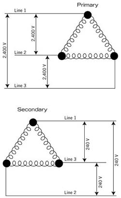
1. Primary In Delta To Secondary In Delta
Figure 1 shows a three-phase service transformer with a Delta primary and a Delta secondary. The ratio of turns of windings from the primary to the secondary is 10 to 1, thus it has a 10:1 turns ratio. This means that the primary windings have 10 times more turns than the secondary.
This turns ratio will cause a voltage drop from the primary to the secondary windings because of the reduced turns of wires in the secondary windings. Fewer turns of wire cause less electromagnetic force field to be intercepted in the secondary windings.
In previous articles, I explained that line voltage and phase voltage are the same in a Delta configuration. This is because one phase is between the two lines of power – therefore, line voltage equals phase voltage for both primary and secondary windings of the transformer. This will not hold true for the Wye configuration, which will be covered later in this article.

Figure 2 shows a three-phase service transformer with a Wye primary and a Delta secondary. It has a 10:1 turns ratio. In the Wye configuration, the line voltage is not equal to the phase voltage.
Figure 3 shows that between two lines lie two phases, which are 120 degrees apart. Thus, line voltage cannot equal phase voltage. The phase voltages will be less than line voltages.
Phase voltage equals line voltage divided by 1.73. The 1.73 is the same as the square root of 3, which comes from a trigonometric function cosine. It takes higher mathematics to understand the origin of 1.73. It is always the phase voltages that are induced into the second windings of the transformer (Figure 2).
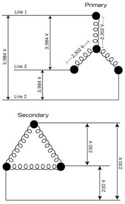
In a three-phase service transformer with a Delta primary and a Wye secondary, there is a 20:1 turns ratio. In the Delta primary, the line voltage equals the phase voltage. In the secondary, however, the line voltage and the phase voltage differ by the factor 1.73. This is because between any two lines, there are two phases that are 120 degrees apart. Notice that the phase voltage of 120 V is less than the line voltage of 208 V.
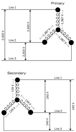
4. Primary In Wye To Secondary In Wye
Figure 4 shows a three-phase transformer with a Wye primary and a Wye secondary. There is a 10:1 turns ratio. Notice that both in the primary and secondary windings there are different phase and line voltages. It is only in a Delta configuration that the line voltage is equal to the phase voltage.
John Tomczyk is a professor of HVAC at Ferris State University, Big Rapids, Mich. He can be reached at tomczykj@tucker-usa.com.
Publication date: 07/07/2003
Looking for a reprint of this article?
From high-res PDFs to custom plaques, order your copy today!


