Cooling From The Depths

Combining Cornell’s lake setting with the scenario Peer paints sets a perfect stage for my mission: to explore the new Cornell Lake Source Cooling (LSC) project, which uses cold water from the depths of Cayuga Lake to cool buildings on campus. This novel system ranks as the first in the world to use deep lake water as a year-round cooling medium, and it saves tremendous amounts of electrical energy and associated pollution. Yet with all its benefits, it took a monumental effort by myriad engineers and scientists to determine its environmental impacts, develop techniques and designs to allay concerns, satisfy stakeholders, and get the project built.
It all starts with the Cornell University chilled water system, which dates back to 1963 and after upgrades over the years, had come to consist of three chilled water plants with eight electric-motor-driven chillers and a 4.4-million-gallon thermal storage tank. All three plants pump into a common underground network consisting of over 10 miles of piping. The Cornell district cooling system operates year round, and it previously delivered more than 16,000 tons of cooling capacity at peak demand and 2,000 tons in winter. It supplies cooling for research processes as well as for general air conditioning of laboratory space, computer rooms, teaching areas, and common spaces. The system serves 75 buildings totaling over four million square feet of air conditioned space, about 40 percent of the core campus.
So why change it? As Peer says, “Several issues came up at the same time. It’s constant catch-up with chilled water.” For starters, six of the chillers used chlorofluorocarbons (CFCs), which are known to deplete the ozone layer in the upper atmosphere and have been banned from production or importation in the U.S.
“We needed to do something big to get rid of CFC refrigerants in our chillers, and that meant either conversion or replacement of the chillers, and it turned out most of them couldn’t be converted to the new chlorine-free refrigerants,” explains Lanny Joyce, manager of engineering, planning, and energy management. Age was another factor, as of three of the chillers were nearly 35 years old. The seventh chiller, a more recent model, was converted to use a non-CFC refrigerant in 1997, and the eighth and most-recently installed unit uses a non-CFC refrigerant. In addition, new cooling loads and renovation were expected to add 10,000 to 15,000 tons to Cornell’s requirement over the next 35 years, and rising energy costs also loomed as a factor.
Steve Little, manager of energy distribution and electrical procurement, recalls that a professor had suggested using Cayuga Lake for cooling when the chilled water system was originally built. It wasn’t considered economical at the time, but the idea would resurface in the mid 1980s, when Little, Joyce, and Bob Land, another engineer in the department at the time, convened an informal concept team. Little remembers sitting around in Land’s office talking about the lake and his experiences sailing on it. Soon after, Joyce raised the idea of using the lake for air conditioning. At the time, they were looking at purchasing a new chiller (number 7), but such a small increment of growth didn’t justify a wholesale change in the system.
But when the Montreal Protocol showed up in 1992, and calls for eliminating CFC refrigerants resulted, the picture changed. The team picked 2005 as a year to be CFC refrigerant-free. Joyce relates, “That’s really what started solid planning on what to do next.” He muses how he and Little began passing numbers over the office partition on converting the system to lake cooling.

Attractive Features
Lake source cooling offered several enticing advantages in eliminating refrigeration equipment and associated refrigerant-related problems and reducing pollutants produced in the generation of electricity in power plants, including carbon dioxide, sulfur dioxides, and nitrogen oxides. This would, in turn, reduce the potential for global warming and acid rain. LSC would also offer a 75 to 100 year system life, instead of the 30 to 40 years typical for chillers.Joyce says a team at Xerox in Webster, N.Y., on Lake Ontario had looked at a lake cooling system, but Xerox couldn’t spend the money because the company was struggling at the time. “It turns out the engineering team they hired was all tuned up and ready to go, thinking about deep-water-based cooling, so we hired that team to do a brainstorming session.” This involved bringing engineers and planners together and imagining the future, costing things out, and doing a small amount of engineering. After two days in 1994, they had produced a pre-feasibility study saying that lake source cooling could be done cost effectively. A subsequent Phase I Feasibility Investigation revealed that an LSC plant, in combination with non-CFC chillers, would prove more economical to operate than a system based exclusively on chillers. The team concluded it could market the concept.
Looking for quick answers on air conditioning, heating and refrigeration topics? Try Ask ACHR NEWS, our new smart AI search tool. Ask ACHR NEWS
According to Little, they determined they had to structure the rollout of information properly to get the idea past all the roadblocks that would come. “We actually engineered the dialogue with everybody. We rolled out a plan for managing the communication side, and what came out of that was a list of 19 permits and an understanding that we needed to have a permitting team.”
At this stage, pre-feasibility people dropped out, and a design group formed and starting working with a permitting team on Phase II. As Joyce recalls, “One of the things that was really important in the success of the project was recognizing that we needed parallel tracks of permitting, outreach and communication, and engineering.” Bob Land developed a plan for this, and the group pursued an environmental impact statement. “As early as the summer of 1994, we were out on the lake taking data, because we knew that getting data on the lake’s condition was going to be really important in modeling the impact of the project on the lake’s ecosystem. All of us committed early in the project that if we came up with a belief the project would be harmful to the lake, we wouldn’t continue it.”
As Joyce tells it, everyone they presented their case to said it made sense. “The atmospheric environmental benefit for not using electricity is huge, and the extra heat to the lake and the exchange of nutrients from a water chemistry standpoint by moving water from one point of the lake to another and the biological impact, all those were very small to imperceivable.” He adds, “One professor in civil engineering said, ‘We can’t afford not to pursue engineered reductions that impact the environment.’” The Cornell Board of Trustees approved funding for Phase III Final Design and Construction in January 1998.
After four years of environmental study, the New York State Department of Environmental Conservation (DEC) approved Cornell’s proposed LSC plan in 1998. The DEC required Cornell to include many special features in the project to minimize impacts, and they required the university to carry out a lake monitoring program to verify its safe operation. Construction began in spring of 1999, with startup and commissioning occurring during the summer of 2000.
Peer explains that he, Joyce, and Little carried out the engineering on the project, with help from consultants, because their roots run deep at Cornell. All three are Cornell graduates and licensed P.E.'s. Little has worked at the school since 1982, Joyce 1984, and Peer 1991. Joyce is a mechanical engineer, while Little is an electrical and energy engineer. Peer studied agricultural and biological engineering and later became a mechanical engineer. Each took charge over separate sections of the project. Peer says on projects like this, “We actively manage the design because we have to live with it in the end.”
Peer found himself dealing with many disciplines in the project, including mechanical, civil, and electrical. “That’s what’s really cool about my job. I’m a mechanical engineer, but I get involved in electrical and civil as well.” Calling himself the “the process guy,” he was responsible for melding the major components in the system so they’d work together.

Consultants Clamored For Work
But there was plenty of work to go around for outside consultants, too, Little says. “We had a lot of people involved.” Having no restraints on who they hired, “We started asking questions of the best we could find.” They found a person nearby who was a foremost expert in water sampling for lakes in the Northeast. They found a Ph.D. working at Stearns & Wheler, an environmental engineering firm in Cazenovia, N.Y., who was a foremost expert in deep freshwater lake ecology, particularly the Finger Lakes. Five individuals at Stearns & Wheler later approached them about working on the project, and the firm handled environmental review and permitting.Momentum built as word got out about the project, Joyce recalls. “People wanted to work on the project.” A deepwater sonar expert solicited them. A German professor assisted with studying the hydraulics of the lake and water mixing. They solicited the premiere expert on plastic pipe from Belgium and brought in from Hawaii the only consulting firm in the world that had laid the type of intake pipe they proposed. Makai Ocean Engineering, a company that provides ocean engineering services worldwide, has designed a number of polyethylene intake pipelines and has done extensive work with seawater air conditioning.
Another key player, Gryphon Engineering, had worked with Cornell for 25 years on utility projects and developed a strong relationship with them. Located in St. Catherines, Ontario, Canada, the company provides civil, structural, mechanical, and electrical engineering for all aspects of power generation, utility, and distribution projects, including chilled water plants. Acres International, a Canadian engineering and planning firm with offices in New York state and Seattle, handled civil design.
With all the environmental ramifications involved with the project, having in-house engineers handle core engineering may have been the only way to go, Little says. “This wouldn’t have happened if we hadn’t been local here. An outside engineering firm couldn’t have done it.” As Joyce says, “We were active members of the community, we were long-term residents of the area, and once we decided this was the right thing to do for the environment and for Cornell, we put our heart and soul into making it happen.”
In describing the engineering work involved, Little says, although the concept wasn’t new, “We did a great deal of applied research. We were doing things that hadn’t been done before.” For example, Joyce points to the lake water intake and piping, “That’s absolutely unique.” This was the first pipeline Makai had ever done in a freshwater lake, and it required solving several problems. To keep it from collapsing under suction, they placed collars around it. While the currents and waves in the lake were small compared to those in the ocean, they were large enough to require a unique anchoring system to hold the pipe due to the weak sediments covering the lake bottom. Steel shear plates were designed to be coupled to concrete pipe anchors, and these plates were driven into the bottom after pipeline deployment. Makai subcontracted Haley and Aldrich, a geotechnical and environmental engineering firm based in Boston, to assist in geotechnical investigations.
Such large-diameter deep pipelines see substantial loads during installation, and Makai conducts field research studying their installation and loading. They develop methods for assembling the pipe onshore, where labor costs are lower. After heat-fusion welding sections of pipe together, contractors deployed the assembled floating pipe from the surface using a controlled sink process of pumping water in at the shallow end and releasing air at the other.
Joyce adds, “Nobody’s ever built an intake at 250 feet before with a removable screened intake. Makai actually came up not only with a removable screen that we can bring to the surface, we can also actually retrieve the entire intake pipe to the surface. The last 600 feet of it can come up in an arc from the bottom.” Makai fabricated a 1/10 scale model of the pipeline and tested it off their pier in Kailua, Hawaii. The recoverable intake structure would allow for inspection and maintenance without the need for decompression diving. The last 600 feet of pipe were lightly weighted, and the intake structure was designed with special buoyancy modules that allow it to float on the surface when filled with air.
Another area that required innovative design was the 28-foot-deep wet well where lake water enters the Heat Exchange Facility. Known as a siphonic system, this arrangement allows water to flow through the intake to the plant by gravity. At no flow, the water levels in the wet well and at the lake stand equal. As water starts to flow through the plant, the wet well level drops below lake level, and the resulting difference forces lake water to flow into the wet well by gravity. Acres International built a scale model of the wet well in the Canadian National Hydraulics Laboratory and used similitude relationships to predict how it would work.
Civil Engineer’s Dream
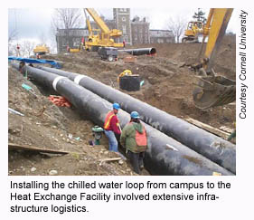
Although the work sounds like a mechanical engineer’s dream, it actually became more of a civil engineering project because of having to dig up roads and dealing with other infrastructure to lay the pipelines to the heat exchanger plant. “It was a mess,” Peer says about burying the chilled water loop from the lake to campus through two-plus miles of residential neighborhoods, shopping areas, and schools between the lake and campus. In one example, Peer explained how they had to run the intake and outfall pipelines under a railroad and highway to get from the lake to the heat exchanger building, and this took elaborate excavating and boring to do it without disturbing the rails.With the LSC system now in place, it can generate up to 20,000 tons of cooling. It wasn’t designed to handle the maximum campus cooling load. At peak loads, and for backup, the two chillers that remain and the thermal storage tank supplement the LSC system.
Joyce reports that with all the design effort they put into LSC, they got “better than expected results in the end. It’s easier to operate than we anticipated, we’re actually saving more energy than we anticipated.” He adds, “Our appetite for cooling at the campus continues to grow, so the benefit for having lake source grows along with it.” It reduces the campus energy use for cooling by 80 percent. The project has saved 30 million kilowatt-hours of electricity since July 2000, equating to 25 million pounds of coal and $1.5 million a year.
The project cost $58 million, higher than simply replacing the old chillers with new. The team did a 30-year analysis on the project and calculated a 10- to 12-year payback. Most companies would scoff at such a long-range return, but Peer says, “This is a long-term solution to the university’s cooling needs. Our philosophy is that Cornell’s going to be here forever.”
With the dust settled now, literally and figuratively, the team has had a chance to reflect on their venture. “It was fun to do, but it was stressful,” Joyce reveals. “This was a big commitment. For me it was a seven-year effort. We were all glad when it ended because we couldn’t have maintained that level of intensity for another year. I think we would’ve cracked.” Peer adds, “It was definitely a career maker for a number of people.” And Little says, “This was a cool project. Everybody wanted to work on it. And they wanted to work on it with passion. That’s the common denominator.”
With Cornell’s system in place and some experience under its belt, people may wonder about the potential for lake source cooling in other locations. “There are definitely other places doing it,” Little states. You need ample cold water nearby and a big enough scale to make a project affordable. “As soon as you say that, you limit the general application to maybe 50 sites in the world. Cities on the Great Lakes can do this such as Duluth, Minn.; Milwaukee; Toronto; and Rochester, N.Y. South Lake Tahoe in California is another example.”
In fact, Toronto already has a major project underway to draw cooling water from Lake Ontario. Engineers and planners there have eagerly awaited results from Cornell’s project, and some team members have ventured north to work on the project. As Little says, “The spinoffs of this job from an engineering and construction standpoint are going to continue for quite awhile.”
Sidebar: Let’s Get Technical — How The Cornell Cooling System Works
The Cornell Lake Source Cooling project consists of three major sections: a lake water intake and return line, a heat exchanger plant, and a chilled water loop. Water from the bottom of Cayuga Lake goes to the Heat Exchange Facility on the lake, which cools water in the chilled water loop, actually a closed loop running between the plant and campus. Because this is done through heat exchangers, no lake water ever mixes with Cornell’s chilled water. To provide air conditioning in buildings, water from the chilled water loop passes through air handling units, and cool air is blown into the spaces.The water intake pipe extends 10,400 feet from shore and is made of 63-inch polyethylene pipe with a 3-inch wall thickness. The outfall, or lake water return line, is a 48-inch polyethylene pipe approximately 750 feet long. The last 100 feet of the outfall has 38 six-inch nozzles about a foot above the lake floor in 14 feet of water. This helps promote mixing of the return water into the receiving water.
Cayuga Lake is a deep glacial lake in a land of long cold winters, explaining its desirability as a cooling water source. Lakes form thermoclines — layers of water at the same temperature — throughout warmer months as the surface warms. In winter, the water cools from the top down and becomes mostly the same temperature. The LSC system pulls water off the bottom at a depth of 250 feet, where the water temperature stays 40 degrees F year round.
Three vertical turbine pumps with a design point of 13,000 gallons per minute (gpm) at 80 feet of head and rated at 350 horsepower circulate lake water from the wet well in the Heat Exchange Facility through the heat exchangers and back to the lake. Variable frequency drives control pump outputs, with speed controlled automatically based on the number of heat exchangers in operation.

The seven heat exchangers are counterflow plate-and-frame type each with 665 thin metal plates. They’re piped in a parallel arrangement allowing any combination of pumps and heat exchangers to come on-line to meet system requirements. Motorized valves on the lake and chilled water piping allow the control system to automatically add or remove units from the process as needed. Water coming from campus at 60 degrees F is cooled to 45 degrees F, while intake water from the lake at 40 degrees F is heated to 52 degrees F.
The facility is essentially unmanned and the process automated. A programmable logic controller (PLC) serves as the process control system. Operators interface with personal computers that communicate with the PLC, Cornell’s Central Heating Plant (CHP), and chilled water plant control systems via Ethernet. A dedicated fiber optic link connects the Lake Source Cooling facility with the CHP.
Sidebar: Facing Environmental Questions
To address environmental concerns people would have about Cornell’s Lake Source Cooling project, Steve Little, Cornell’s manager of energy distribution and electrical procurement, says early on, “We sat down and drew up a list of about 20 questions that grew eventually to 100. We directed our teams to start finding answers before the questions were asked.”A foremost concern was the amount of heat the project would add to Cayuga Lake. The team determined the total heat added by the warmed return water is equivalent to that caused by an additional four to five hours of sunlight on the lake's surface a year. The added heat dissipates each winter and will have no measurable effect on water temperature, stratification, or ice cover, they said. As a comparison, Lanny Joyce, manager of engineering, planning, and energy management, says a fossil-fuel electric power generation plant on the lake uses lake water for cooling and adds 25 times as much heat.
Another concern centered on the amount of dissolved phosphorus that would be brought from the lake's depths to the region of the outfall, where it returns to the lake at a shallower depth. The chance of impact on summer algae growth was deemed low, and no discernible change in lake clarity was projected.
Looking at possible future cumulative effects, what if every municipality, company, and institution on Cayuga Lake lays claim to its depths for cooling water? “That was one of the very first questions asked,” Little states. Only one other town of any size lies on the lake. “There isn’t any other developed infrastructure in place that could tap the resource.”
Several design steps taken by the team involved biological measures dictated by New York’s Department of Environmental Conservation. Concern arose that certain fish and Mysis relicta, a species of small shrimp that fish eat, might be drawn into the intake pipe. Some Mysis relicta are active at the intake level, but they avoid light, so the designers incorporated two eight-watt lights to deter the shrimp and high-frequency sound to repel alewives.
They designed the recoverable stainless steel screen on the intake pipeline to keep fish and other aquatic species out, and surface recovery of the screen allows it to be cleaned of the zebra and quagga mussels known to clog water system intakes. This came as part of an effort to design the pipeline so it can be cleared of mussels by physical rather than chemical means. When the need arises, they can run a device known as a pig through the intake pipe using water pressure. Made of foam rubber with a polyethylene jacket, it takes up the full inner diameter and scours the walls.
Reprinted from Progressive Engineer, an online magazine and information source covering all disciplines of engineering from a human perspective. To view it, visit www.progressiveengineer.com. Based in Lewisburg, Pa., Tom Gibson is publisher and editor of the publication as well as a mechanical engineer and freelance writer.
Publication date: 05/05/2003
Looking for a reprint of this article?
From high-res PDFs to custom plaques, order your copy today!


