Chiller Design for Low-Lift Conditions
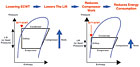
Figure 1: In comfort-cooling applications, lower ECWT indicates lower lift.
For a centrifugal chiller to operate efficiently with higher LCHWT, certain features are required, which may not be standard on many chillers unless specified. To understand the importance of these features, it is necessary to understand the thermodynamics of lift and its relationship to chiller performance. This knowledge will facilitate proper chiller selection for process-cooling applications with low-lift conditions.
UNDERSTANDING LIFT
Lift (or head pressure) is the difference between condenser refrigerant pressure and evaporator refrigerant pressure. Using defined pressure-temperature relationships, lift can also be measured with the LCHWT and the leaving condenser-water temperature. Further, when the LCHWT and condenser-water flow are constant, the ECWT can be used as a metric for lift. Because most condenser water systems are designed for constant flow, ECWT is the most common metric for lift, and we will use it in this article.
FIGURE 2: In process cooling applications, higher LCHWT means lower lift.
LIFT IN COMFORT COOLING
In comfort-cooling applications, lower ECWT indicates lower lift, which lowers the compressor work (Figure 1). The relationship can be summarized as: lower ECWT = lower lift = lower compressor work = lower energy usage. In comfort-cooling applications, ambient weather conditions often allow facility owners to take advantage of ECWT as low as 50° (at AHRI conditions).The capability to use lower ECWT significantly improves chiller efficiency. In fact, greater chiller efficiency can be achieved by lowering lift than by lowering load. The efficiency improvements due to lower lift can be realized in both single-chiller and multiple-chiller installations.

FIGURE 3: An open-drive motor is located outside the refrigerant circuit.
LIFT IN PROCESS COOLING
In process-cooling applications, LCHWT is the metric associated with lift: higher LCHWT means lower lift (Figure 2). So for process-cooling applications with low-lift conditions, the formula changes slightly: higher LCHWT = lower lift = lower compressor work = lower energy usage.But the chiller must be de- signed to take advantage of higher LCHWT to see effective reduction of compressor work. If it is, then process facilities will also see significant energy savings because efficiency is mostly impacted by lift and only slightly impacted by load. These efficiency improvements will be seen in both single-chiller and multiple-chiller installations.
SELECTING CHILLERS DESIGNED FOR HANDLING LOW LIFT
Not every chiller is designed to take advantage of conditions when high LCHWT is specified. In fact, there are four design variables that affect a centrifugal chiller’s ability to handle low-lift conditions encountered in process-cooling applications:1. The drive design;
2. The orifice design;
3. The oil management system; and
4. The compressor aerodynamics.
The drive design: It is not immediately obvious that the design of the electric motor should have anything to do with a chiller’s ability to handle low-lift conditions, but it does.
There are two basic motor choices for centrifugal chillers: refrigerant-cooled (hermetic-drive) or air-cooled (open-drive). A hermetic-drive motor is located inside a refrigerant-filled motor cavity. Unfortunately, this is a bad place to be under low-lift conditions.
At all conditions, head pressure on a hermetic-drive motor must be high enough to ensure that refrigerant flows adequately through the motor cavity. Without sufficient flow, current draw can overheat the motor windings, and the chiller will shut down due to high motor temperature.
For that reason, chillers with a hermetic-drive motor must maintain a greater pressure differential between the evaporator and the condenser to ensure adequate motor cooling. A common method for ensuring sufficient pressure differential for hermetic-drive chillers is to artificially limit the lift reduction. Limiting lift reduction will increase the compressor’s energy consumption.
An open-drive motor is located outside the refrigerant circuit (Figure 3). Therefore, it can be air-cooled (or optionally water-cooled). It does not depend on refrigerant flow for cooling and is, therefore, unaffected by changes in refrigerant flow during low-lift conditions.
The orifice design: The orifice is the chiller component that creates a refrigerant pressure drop between the condenser and the evaporator. There are two orifice-design options: fixed or variable.
With a fixed orifice, it is difficult for a chiller to perform efficiently under low-lift conditions at full loads. That’s because fixed orifices are sized for the high head pressure that exists at design-lift conditions. As a result, fixed orifices are simply not large enough to allow the required refrigerant flow at low-pressure conditions.
The variable-orifice design, however, is more accommodating. A variable-orifice valve automatically modulates to maintain proper refrigerant flow, taking into account the head pressure across the valve.
At design-lift conditions, the variable orifice is partially closed, and at low-lift conditions, it opens to allow the proper refrigerant flow. This feature is especially important for multiple-chiller plants where additional chillers and associated auxiliaries (pumps, towers) have to operate to meet building demand.
Without a variable orifice, the operator may resort to running more chillers and more associated auxiliaries than needed because the chillers are unable to load-up. This is an extremely inefficient way to operate a chiller plant.
To avoid the full-load problem of fixed-orifice chillers under low-lift conditions, some chiller manufacturers maintain a high minimum ECWT, up to 75°. But the strategy to increase lift (head pressure) to maintain chiller stability sacrifices chiller efficiency in situations where low-lift conditions would be available to slash operating costs.
In terms of chiller design, the only way to achieve both full-load cooling capacity under low-lift conditions and off-design energy performance is to use a variable orifice as a refrigerant-metering device.
The oil management system: Low-lift conditions also impact a chiller’s oil management system. For example, hermetic chillers under low-lift conditions could lose oil at an increasingly faster rate through the motor bearings and refrigerant-gas seals.
When this happens, large amounts of oil will enter the refrigerant circuit and migrate to the evaporator. Normally, excess oil should reside in the oil sump of the compressor. But if oil is in the evaporator instead, the chiller may shut down on a low-oil-pressure safety.
In addition, the excess oil in a flooded evaporator migrates to the top layer of tubes. But this is where the best heat transfer (refrigerant boiling) occurs. Therefore, when refrigerant in this area is displaced by oil, heat transfer and chiller efficiency suffer significantly.
Open-drive centrifugal chillers are able to use an oil management system that can make oil loss a relatively minor issue at low-lift conditions. For example, an oil-eduction system can be employed to separate oil from the refrigerant in the evaporator and return it to the oil sump. With this type of system, more oil stays in the sump, permitting the chiller to operate effectively at low-lift conditions.
The compressor’s aerodynamics: The design of a centrifugal chiller’s compressor is also critical to low-lift performance. That’s because a centrifugal compressor operates most efficiently when the tip speed of its impeller is optimized for the application.
In a direct-drive compressor, where the impeller is directly connected to the motor, the only way to adjust tip speed is by changing the size of the impeller. Because there are relatively few impeller sizes to choose from, compressor tuning is limited and performance suffers accordingly.
On the other hand, in a gear-drive compressor, tip speed is a combined function of impeller size and gear ratio. With multiple impeller combinations per compressor size, and multiple gear combinations per impeller size, it is easier to select a gear-drive compressor that will match the low-lift application’s requirements most efficiently.
SUMMARY
Centrifugal chillers that can adapt to low-lift conditions where head pressure is reduced because of high LCHWT are able to save energy in many process-cooling applications. To take advantage of low-lift conditions, the chiller should incorporate an open-drive design to ensure proper motor cooling, a variable orifice to ensure proper refrigerant flow, an oil-eduction system to maintain oil in the sump, and a gear-drive compressor to optimize impeller tip speed. A chiller equipped with these four critical design features can deliver superior performance in low-lift conditions and provide significant energy savings in a wide range of process-cooling applications.Publication date: 05/12/2008
Looking for a reprint of this article?
From high-res PDFs to custom plaques, order your copy today!


