Fossil Fuel Heating Equipment: Principles And Troubleshooting
Heating System Principles
Forced-air heat is generated at a central furnace and is then distributed and delivered to the conditioned space via a duct system. A properly designed heating system will generate quiet, filtered, and comfortable air into the conditioned zone. Modern systems have been recently designed that will also filter the air electronically, modulate airflow as zone temperatures change, and bring in fresh outside air based on occupied time.There are three types of fossil fuel heating systems predominantly available on the market today. These include natural gas, liquefied petroleum (LP), and fuel oil forced-air furnaces.
Fossil Fuel Forced-Air Heating
Forced-air fossil fuel furnaces are factory manufactured, packaged heating units that include: a combustion chamber designed for gas or oil, a heat exchanger, a flue gas exhaust chamber, a forced air circulating fan, and a controller section. Newer units often include a secondary heat exchanger to increase efficiency and an auxiliary fan for combustion gases. Since the newer units substantially cool the combustion gases, removing water vapor from the combustion gases, they are often called condensing high-efficiency furnaces. Additionally, they will have plastic flue gas piping instead of older more traditional metal flue pipe since the gas temperatures are much lower than less efficient units.Older standard gas furnaces were 65-78 percent efficient, while newer high-efficiency furnaces are 78-85 percent efficient when used with induced draft fans. Modern condensing furnaces, however, are 90 percent efficient, and the pulse-type furnaces can operate at up to 95 percent efficiency.
Modern fossil fuel furnaces also come equipped with electronic controls for ignition, fan speed control, electronic thermostats, and safety controls. The operating pressure of the natural gas furnaces at the burner is 3.5 inches of water column.
Natural gas is predominantly used as the preferred fuel in larger cities and communities where main gas lines are available. Fuel oil and LP heating furnaces are more popular in rural communities.
Fuel oil (diesel) furnaces are similar to gas furnaces except that the fuel must be pumped and atomized within the furnace combustion chamber, since it is provided to the customer in the liquid state. Plus, the atomized oil must be ignited with high-voltage electrodes.
The components within LP heating furnaces are almost identical to traditional natural gas furnaces, except the operating pressure of the gas at the burner is typically 11 inches of water column.
The temperature of the zone is controlled by controlling the combustion process as needed for the conditioned space. This often requires a pre-purge, flame proof and verification, combustion cycle, and post-purge upon completion.
Troubleshooting Fossil Fuel Forced-Air Heating Furnaces
When troubleshooting the fossil fuel forced-air furnace, it is important to break the unit down into three basic components:Testing The Thermostat Control System
The thermostat control system on any gas or electric heat furnace follows a basic design. It is comprised of three wires: a green wire for manual fan control, a red wire for 24-volt AC power, and a white wire for the main heat control signal back to the furnace. When troubleshooting the thermostat, it is important to first verify that 24-volt AC power is available at the transformer secondary and at the thermostat. Once this is verified, then you should use a digital multimeter (DMM) to check for voltage at the white wire coming from the thermostat.If power is available at the transformer, but not at the outlet of the thermostat, then the problem is with the thermostat. If the power signal is available at the white wire at the outlet of the thermostat, but is not powering up the main gas control system, check for an open safety switch or loose connection at the gas valve or gas control module.
Testing The Fan Control System
Like the thermostat, the fan control system, which automatically turns on the fan, is simple and straightforward. On older furnaces, the fan will turn on when the combustion plenum reaches a predetermined temperature. On newer furnaces, this control is a function of time, not temperature.To troubleshoot the fan plenum control system, first verify that the plenum combustion chamber is getting hot. If it is not hot, check the main gas valve and combustion controls. If it is hot, and the fan is not running, check the condition of the fan motor. It is possible that it has failed due to seized bearings. While the power is off, check to see if the fan spins easily. Check the combustion fan control on the side of the combustion chamber to make sure it isn't stuck open and preventing the fan from running. This can be done with a clamp meter. Check for an open or closed combustion switch. It is possible the switch has failed due to age or dirt buildup on the bi-metal element which resides within the combustion heating chamber.
If the fan is running and you want to determine if it is set at the proper speed, then you need to check the temperature difference across the combustion heat exchanger. This requires measuring the return air temperature and the discharge air temperature. These temperatures can be checked by using a digital recording thermometer to log the temperatures. The normal temperature difference is about 40-70 degrees F. Note that this will vary depending upon the equipment manufacturer's design of the heat exchanger surface, so be sure to look at the manufacturer's specifications within the unit for acceptable temperature difference variations.
Testing The Flame Verification Control System
Checking the flame verification control system is required as part of the troubleshooting process when a flame will not stay lit on a gas or oil furnace. Fuel oil heating furnaces use several types of flame verification systems. Older gas furnaces use a thermocouple with a millivolt signal to verify flame condition. Newer, more efficient gas systems utilize various electronic flame verification systems. Oil furnaces use a cad cell with a resistance output to the controllers. Some manufacturers tried using a temperature actuated switch mechanism.This article will only address the most popular flame verification systems, including the thermocouple, flame rod system, and cad cell system.
Testing the thermocouple.
To test the condition of the thermocouple, you simply measure the output signal of the thermocouple with a DMM. This is accomplished by unscrewing the thermocouple from the gas valve and attaching the leads from your DMM to the positive and negative polarities of the thermocouple. Normal output signals of the thermocouple when heat is applied to the tip are 20-30 millivolts.
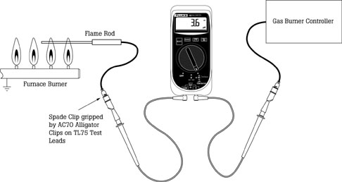
Most of today's light commercial and residential gas burner controls utilize a flame rod to confirm the presence of the flame. Here's how it works: The control center sends out a voltage to the flame rod. The flame itself serves as a partial diode rectifier between the flame rod and the ground. Without a flame, the circuit is open and there is no current. However, the presence of a flame will allow a few microamps of DC current to flow. The acceptable microamp reading varies from one manufacturer to another. Some controllers such as the Honeywell Smart Valve yield only 0.6 microamps under full flame. However, it is more typical to find readings around 3 to 4 microamps such as with the White-Rodgers controller.
The test procedure itself is simple.
1. Shut off the furnace and locate the single wire between the controller and the flame rod. Typically, the wire is terminated at the control panel or the flame rod with standard spade connectors.
2. Break the spade connection and place the test leads from a DMM that measures microamps in series into the circuit. Having alligator clips for the test leads will make the connection much easier.
3. Turn on the meter and set it in the DC microamp (mA) mode. Restore power to the furnace (follow furnace manufacturer's instructions for safe operation) and set the furnace to call for heat.
4. Once the burner or pilot ignites, check your meter reading. Refer to the furnace troubleshooting instructions to determine how to proceed with this result. Typically, a low or zero microamp reading may indicate several potential problems including:
a. The flame sensor is not close enough to the flame.
b. Carbon buildup on the rod is limiting current flow (clean flame rod with steel wool).
c. The flame rod is shorted to ground.
d. Continuity is not present between the control module and the flame rod (use the meter's continuity function to check).
e. The control module is bad and needs to be replaced. Verify using the equipment manufacturer's manual.
Testing the cad cell.
Most of today's light commercial and residential oil burner controls utilize a cad cell to confirm the presence of the flame. These systems work in the following manner:
1. On a call for heat, the oil combustion controller center sends out a voltage signal to the oil igniters and oil pump.
2. The igniters start the combustion process. The flame light serves as the energy source which powers the cad cell.
3. As light increases, the resistance goes down. As the resistance goes down, the controller verifies the flame condition and continues to allow the oil pump to operate. If the oil pump fails or oil pressure is lost, the cad cell sends a much higher resistance to the control and the oil pump shuts off on a manual reset. Without a flame, the circuit opens up and there is no oil pump pressure delivered to the combustion chamber.
The test procedure is simple. Shut off the furnace and locate the two wires which come from the cad cell, between the controller and the cad cell. Remove the cad cell from the oil furnace. Typically, the wires are terminated at the control panel with standard spade connectors. Break the spade connections and place the test leads from a DMM in parallel with the cad cell. Having alligator clips for the test leads will make the connection much easier.
Turn on the DMM and set the meter in the ohms mode. Read the resistance with the cad cell exposed to the light within the mechanical space. If the light is not bright enough, shine your flashlight into the cell surface of the cad cell. As the light is increased, the resistance goes down to approximately 1,500 ohms.
Next, cover the cad cell with a piece of black electricians tape. The resistance should go up to approximately 100,000 ohms. If the cad cell does not respond to a change in light intensity, it has gone bad and needs to be replaced. If the resistance does vary between 1,500 and 100,000 ohms as light is added or removed, it is probably operating properly, and you need to look for other problems within the furnace control circuit.
Test Points On Fossil Fuel Furnaces
I. Low voltageII. High voltage on oil furnaces
III. Gas supply
IV. Combustion gases
V. Temperature
Standard older furnaces - 450 degrees F
Mid-efficiency furnaces - 350 degrees F
High-efficiency furnaces 90 percent and up, very cool, uses PVC piping
Greg Jourdan, CM, is a professor and program director of the Environmental Systems and Refrigeration Technology Program at Wenatchee Valley Community College in Wenatchee, Wash. He also serves as an HVAC product consultant for Fluke Corporation. For more information, send e-mail to gjourdan@msn.com.
Publication date: 01/12/2004
Looking for quick answers on air conditioning, heating and refrigeration topics? Try Ask ACHR NEWS, our new smart AI search tool. Ask ACHR NEWS
Looking for a reprint of this article?
From high-res PDFs to custom plaques, order your copy today!


