Tips for a Successful Refrigeration

Whether you are new in the field or have been installing refrigeration systems for years, you can benefit from some installation refresher tips. Here are 10 tips for a successful refrigeration system installation.
1. Read the installation manual.
An installation booklet almost always comes shipped with a piece of equipment. You may have put that information in a file or even thrown it out. But have you ever read through it?
It contains helpful information that can save you time and money. Instructions, along with drawings, charts, and diagrams, help you get the most out of your equipment.
A majority of the questions and problems could be answered or prevented by consulting the installation manual. It covers the basics, but also provides specific guidelines for special situations that you may not have run across before. Look through it and chances are you will find something useful.
2. Take care in expansion valve selection and adjustment.
Where the nozzle is a distribution device, the expansion valve is a metering device. Proper thermostatic expansion valve adjustment for superheat can increase the efficiency of the evaporator, give you better system balance, and more efficient operation.
Looking for quick answers on air conditioning, heating and refrigeration topics? Try Ask ACHR NEWS, our new smart AI search tool. Ask ACHR NEWS
The expansion valve basically controls the volume of refrigerant entering the evaporator coil. This is accomplished by controlling the superheat leaving the evaporator. A properly sized and adjusted expansion valve will adjust to the varying evaporator load and frosting conditions, allowing the evaporator to function at maximum capacity.
An improperly adjusted expansion valve can reduce the capacity and efficiency of the refrigeration system. If the system is operating with an expansion valve that is too small, the evaporator will be starved, lacking adequate refrigerant, and preventing the system from cooling enough. That can also happen with a poorly adjusted expansion valve that allows high superheat to elevate the evaporator.
By contrast, if the expansion valve is too large, the valve will tend to “hunt” or have large swings in superheat temperatures, leaving the system off balance and negatively affecting system capacity and efficiency.
The expansion valve should be selected for the condensing unit capacity and not the evaporator capacity. The condensing unit is the dictator. That’s what is actually pumping this capacity and removing the heat.
Many people believe that the manufacturer presets expansion valves. They are not, however, preset for your specific application. Make sure you know the capacity of your condensing unit and follow the tables for expansion valve selection.
3. Take care in evaporator placement.
Refrigeration equipment refrigerates air within an insulated space. The air, in turn, refrigerates the product, so proper air distribution and circulation is critical.
Oftentimes poor product temperature is blamed on refrigeration equipment when the problem is actually poor air distribution and circulation. The best way to prevent this is by correctly configuring evaporator placement. From the evaporator, air must freely circulate in and around the product and return back to the evaporator.
You have two useful resources to help you get the best evaporator placement. First, the installation manual outlines minimum space requirements away from walls and between units. It also provides tips like, “Always avoid placement of unit coolers directly above doors and door openings.”
Second, talk to your end user. Make sure you have a complete understanding of where product will be stacked, where light fixtures will be placed, and where shelves and racks will be located. Once you know this, you can adjust equipment placement accordingly.
If there is a conflict between optimal unit placement and end user intentions, make sure you address this while both you and the end user can still make compromises. Remember that the end user will call you if the product is not holding temperature.
Also, take into consideration accessibility to the unit for future service and maintenance. It is not enough to get the unit in place. You must have access to end panels, drain pans, etc., to be able to work on it later.
4. Follow good piping practices.
Correct system piping is essential for proper system operation and adequate oil return to the compressor. For oil return, the suction pipe is the most critical. The suction pipe should slope toward the compressor and should be sized for minimum pressure drop and proper refrigerant velocities.
Select pipe sizes carefully. If the pipe size selected is too large, the refrigerant velocity becomes insufficient to carry oil vertically up to the compressor when the compressor is above the evaporator. The oil must pass freely through the entire system and reach a state of equilibrium to maintain stable oil levels in the compressor.
Equally important in system piping design is the use of traps in the suction line. Most technicians get the pipes properly pitched downhill so that the oil flows down toward the condensing unit. But you get into situations where the oil has to go up, so you can’t rely on gravity. You have to rely on a trap that acts as a collection point for the coil and aids in moving that oil up through the coil.
A p-trap should be used at the base of any suction riser greater than 3 to 4 ft in length. A suction riser is any vertical line that has an upward refrigerant flow. In long suction risers, p-traps should be used for each 20 ft of vertical rise.
In addition, it is good practice to install a p-trap at the outlet of the evaporator if the suction line rises above the bottom of the evaporator. This trap will ensure that oil can flow freely out of the evaporator.
5. Set the defrost.
Defrost must be adjusted to the usage of the refrigerated space. Again, this is something you need to discuss with the end user. Ask, “How do you use this space? What are your busy times? When do you load the box?” Then you can make a good estimate as to what time of the day you want the unit to go into defrost and how many times a day you want it to do that.
You should never set the defrost to occur under the heaviest activity, like when stocking normally takes place. Wait until the loading is over, because when loading is being done, the door is wide open, letting in nothing but moisture and warm air.
A good rule of thumb for starting out is to defrost four times a day, every 6 hrs. Whenever you open the door to a freezer, you let in more moisture. The heavier the use, the more moisture you’re going to collect.
You may end up having to go to six defrosts per day. As a contractor, you need to a do a follow-up to see how it is doing.
On the other hand, the box might be closed up and not opened for days. Overheating the evaporator is not a good situation either, because it throws heat off into the refrigerated space, which can create steam and droplets on the ceiling and other surfaces. If the box isn’t getting much traffic, you might cut back to two or three defrosts a day, which will also save energy.
Another important consideration is defrost termination. Some systems require more manual settings than others. Some evaporators come with fixed defrost, with adjustable defrost optional. The larger units come with adjustable defrost. Adjustable units require fan delay settings.
You need idle time between when the compressor starts running, coming out of defrost, and when the fans come on. After the ice melts, a residue of water is left on the coil surface. If the fans come on immediately, that water is sucked right through the fan and blown all over the product, the ceiling, everywhere. The compressor needs to run long enough to refreeze any moisture left on the coil before the fans are energized.
A good rule for setting the defrost termination switch is to watch your coil in defrost. After all the ice has melted, give it one minute more. Then start adjusting your defrost termination switch to kick it into refrigeration. Just a minute or two after all that ice is melted is all it takes.
6. Evaluate the wiring.
Prior to an installation, you need to evaluate your system and determine the type and gauge of wire required for that particular job. For each length of wire, consider all loads that will be powered on that circuit, including relays, contactors, microprocessors, and solenoids. Add up all of these loads to determine the proper gauge wire.
Measure how long your wire runs are and make sure you have sufficient amperage capability in the transformer and wire gauge to pull in the contactors. The longer the length, the higher the gauge you need to pull the same amperage. The transformer should also be checked to ensure that its VA rating is sufficient.
For long runs of low-voltage power, such as a 24-vac class II control circuit, determining the correct wiring and transformers is critical for the correct operation of low-voltage components. You may find that the wire powering a microprocessor also powers relays and contactors. The wire and transformer should be sized so the operation of the components does not affect the microprocessor.
One sign of not having enough amperage at the microprocessor is the display resetting or flickering when a contactor or relay is energized. This often appears as an intermittent problem that you would see only at the moment the contactor is energized.
In this case, check the transfer’s VA rating first, then make sure all of your terminal connections are tight. If all seems OK, you most likely need a thicker gauge wire. Always refer back to the manufacturer’s installation and maintenance guide.
7. Carry the proper tools for the job.
Everyone should have a good set of general hand tools with them whenever they go out to a jobsite. Along with good general tools, the following should also be included:
Be sure to purchase quality instruments and keep them properly calibrated. Repair or replace worn or damaged instruments and know how to properly use all equipment before you get to a jobsite. You will also need lifting equipment for evaporator and condensing unit placement.
8. Take care in outdoor unit placement.
When placing your condensing unit or remote condenser, allow for plenty of outside air to get to your unit. That includes space away from walls, fences, and other units. Also, make sure one unit’s exhaust is not feeding into another unit’s intake.
Each unit should be located so that air may circulate freely and not be recirculated. For proper airflow and access, all sides of the unit should be a minimum of the width of the unit away from any wall or obstruction. It is preferred that this distance be increased whenever possible.
Also, make sure you are providing yourself enough clearance to come back and service the unit. Make sure all panels can open freely and that you have space to maneuver tools and equipment.
And don’t forget to look up. Overhead obstructions need to be avoided for proper airflow and safety. Without proper clearance, you will eventually run into problems like loss of capacity and higher head pressures, which cause poor operation and potential failure of equipment.
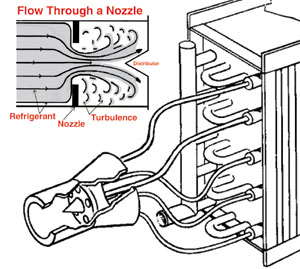
9. Select the distributor nozzle.
Before you install the expansion valve on the distributor of the evaporator, the proper distributor nozzle must be installed.
Most evaporators come with two distributor nozzles: one for R-22 and another for most other refrigerants. The nozzles that are shipped with the evaporator are sized to meet most standard applications. One of these two nozzles will be used in a majority of applications. The manufacturer-supplied installation and maintenance guide provides exceptions and formulas for sizing nozzles should special conditions apply, like subcooling or different temperature differentials.
The distributors in Heatcraft evaporators require nozzles that create pressure drop and help mix the liquid-gas refrigerant. The nozzle also helps ensure that the refrigerant entering the evaporator from the expansion valve is evenly distributed to all circuits. The distributor nozzle creates a turbulence that spins refrigerant equally into all of the distributor tubes. This ensures that the entire evaporator gets fed evenly.
If the nozzle is oversized, the refrigerant tends to take the flow of gravity, going through the oversized opening, dropping to the bottom tubes. You’ll notice one portion fed more than another in coil freezing or sweating. Without proper feeding, the evaporator cannot accept a full-load condition. You’re basically just going to build frost unevenly until you have frozen-up coils with a snowball effect on low suction pressure or floodback on the compressor.
If your nozzle is too small, it acts like a restriction in the system. You starve your coil and end up running very low suction pressures, high superheat, and high head pressure, which can also overheat the compressor and can eventually cause compressor failure.
10. Insulate the refrigerant lines.
A refrigeration system involves a delicate balance of fluid volumes at a particular temperature and pressure flowing through a carefully designed system. To function optimally, fluid temperatures must not pick up or lose heat from the surrounding environment until they are supposed to.
Therefore, after running the final leak test, refrigerant lines exposed to high ambient conditions should be insulated to reduce heat loss or gain and prevent the formation of flash gas in the liquid lines. Proper insulation maintains consistent temperature, allowing the expansion valve and nozzle to work properly.
You base expansion valve size on a certain liquid temperature. If you take the liquid line, which is just a copper tube, and run it through a freezer and it’s 10° in that freezer, by the time that liquid travels 40 ft, it can go from 50° to as low at 10°. By then, standard components like expansion valves and nozzles are oversized and can’t work right.
Suction lines should be insulated with 3/4 -in. wall Armstrong “Armalfex” or the equivalent.

Insulation on the suction line will ensure cooler refrigerant return gas temperature to the compressor for more cooling. This also keeps the motor in the compressor cool.
The environment the pipe is going through determines the thickness. It may be a boiler room, a freezer, or it may go outside of the building. It must be thick enough to prevent condensation on the outside of the insulation. This is determined by the temperature of the suction line you are running and by the R factor of the insulation.
Publication date: 07/02/2001
Looking for a reprint of this article?
From high-res PDFs to custom plaques, order your copy today!


