The Role of the Suction Line Accumulator

The refrigeration compressor is designed to compress vapor only. A suction line accumulator prevents compressor damage from a sudden surge of liquid refrigerant and oil that could enter the compressor from the suction line.
The suction line accumulator is a temporary reservoir for this mixture, designed to meter both the liquid refrigerant and oil back to the compressor at an acceptable rate. This prevents damage to the reed valves, pistons, rods, and crankshafts.
Accumulators have a metering ejector device that picks up liquid, vaporizes it, and returns it to the compressor. This prevents liquid slugging and controls oil return. It is particularly important on hot gas defrost systems, heat pumps, etc., where surges of liquid refrigerant frequently go back down the suction line.
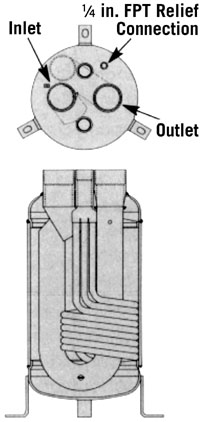
Vertical accumulators use a U-tube or tube-within-a-tube design to draw gaseous refrigerant off the top of the vessel.(See Figure 1.) At the bottom of the U-tube, an orifice picks up a small amount of oil and liquid refrigerant and meters it back with the gaseous refrigerant. The small amount of liquid refrigerant will boil off in the suction line. The oil will be carried with the gaseous refrigerant back to the compressors.
A vent hole at the top of the accumulator U-tube outlet acts as a vacuum break to prevent an accumulator that has flooded during an off cycle from slugging upon start up of the system. ASME accumulators over 6-in. diameter are manufactured to ASME Code, Section VIII. A female pipe connection is supplied for a pressure relief device. A pipe plug is installed in this connection for pressure testing and painting at the factory.
Vertical accumulators should have a heat exchanger coil or a heat element added on low-temperature applications (0?F and below) to help boil off liquid refrigerant and raise the oil temperature to help facilitate oil flow. (See Figure 2.)
The heat exchanger can be used on low-temperature systems to subcool the liquid line while helping to boil off liquid refrigerant in the accumulator by passing the liquid line through the heat exchanger coil. This can increase system efficiency while helping oil flow in the suction line. Do not use discharge gas through the heat exchange coil or there is a risk of overheating the compressors.
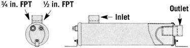
Horizontal accumulators (Figure 3) should not be used when the temperature of the liquid refrigerant is less than 15?F (9?C) in the accumulator. At temperatures below this point, the oil will become thick and will not draw up the dip tube to be metered back to the compressor.
Looking for quick answers on air conditioning, heating and refrigeration topics? Try Ask ACHR NEWS, our new smart AI search tool. Ask ACHR NEWS
Heat bands are available to help boil off liquid and aid oil flow. Do not add too much heat or there is a risk of overheating the compressors. Any heat bank that is added should be installed at the bottom of vertical accumulators and the outlet end of horizontal accumulators.
Selection of a suction line accumulator should be made on the basis of the following three capabilities:
1. The accumulator should have an adequate liquid-holding capacity that can vary with the system. Normally this should not be less than 50% of the system charge. If possible, this value should be checked based on actual tests.
2. The accumulator should perform without adding excessive pressure drop to the system. The recommended maximum tonnages are based on a pressure drop equivalent to 0.5?F. These ratings are those of the accumulator based on oil return through the accumulator, and will be modified by the length of the suction line and compressor displacement.
3. An accumulator should have the capability of returning liquid at the proper rate and under a range of load conditions.
INSTALLATION
Install the accumulator after the suction line filter or the orifice in these accumulators may clog if the oil into the accumulator carries wax or other debris. This is especially important on systems using POE oil.Insulate the accumulator to prevent condensation from forming on the outside. Many customers prefer not to insulate the accumulator to gain some heat transfer from the air surrounding it. But some means of catching the condensation formed is necessary in most cases.
On accumulators with heat exchanger coils, the coil should be connected to the liquid line after the receiver. Since the heat exchange coil is a closed loop, the heat exchange coil “in” and “out” fittings may be switched.
VERTICAL ACCUMULATORS
Install the accumulator in a vertical position as close to the compressor as possible.(Warning: Wrap a wet rag around the base of the copper fittings on the S-7000 Series to prevent damage of the factory- installed braze.)
Connect the suction line from the evaporator to the inlet of the accumulator. Connect the outlet of the accumulator to the suction line of the compressor.
On systems with a reversing valve and on heat pump systems, the accumulator should be installed between the compressor and the reversing valve. The pump-down cycle should precede all compressor shutdowns.
HORIZONTAL ACCUMULATORS
Install the accumulator in a horizontal position with the top of the inlet being level so that the return tube is at the lowest part of the accumulator, leaving a smaller pool of liquid in the bottom of the accumulator. The connection size must be the same as the line size.Connect the suction line from the evaporator to the inlet connection.
Connect from the outlet to the compressor allowing a straight run of 12 in. (minimum) to permit full venturi action. Avoid sharp 90-degree bends wherever possible and use two 45-degree elbows to encourage laminar flow of returning gas.
The accumulators referenced in this article have a ½-in. FPT connection for liquid injection and a ¾-in. FPT connection for hot gas bypass. These connections can also be used as a relief device as required by UL 207.
The accumulator should be supported by the use of two angle brackets. These brackets are designed to be fastened to the stud on each end cap.
TROUBLESHOOTING
On accumulators with fusible elements, if the fusible element leaks, the accumulator must be replaced. The fusible element is a UL requirement for venting of gas during a fire to prevent rescue personnel from injury due to a tank rupture. Soldering over this connection or in any other way preventing the fusible element from melting out to relieve pressure will void UL listing.By removing the insulation on an accumulator, it is possible to observe the level of refrigerant in the vessel in most cases by the level of condensation or frost on the exterior. On systems in which slugging is suspected, observe the vessel during a variety of conditions, especially during defrost cycles.
If refrigerant slugging is witnessed on a system with an accumulator, there are several possibilities for the cause of the problem:
If there is no oil returning from the accumulator and the oil cannot be accounted for by the separator and oil control system, there are a few possibilities for the cause of the problem:
If too much oil is returning to the compressor from the accumulator, it is possible that the oil separator is not functioning properly or that an oil separator needs to be installed. On certain low-temp or flooded systems, it may be necessary to install a higher efficiency oil separator. If a high-pitched whistle from the accumulator is noticed upon initial start- up of the system, ensure that the accumulator inlet and outlet have been piped correctly.
The article was prepared by Henry Technologies. The company can be reached at 800-323-4052; www.henrytech.com (website).
Publication date: 09/03/2001
Looking for a reprint of this article?
From high-res PDFs to custom plaques, order your copy today!


