The Professor: Helical Oil Separators
|
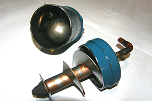
| A helical oil separator. (Photo courtesy Ferris State University) |
Because refrigerants and refrigeration oils are miscible in one another, there will always be some oil that leaves the compressor with the refrigerant being circulated. Also, any time flooding or migration occurs, crankcase oil is sure to be diluted with refrigerant. This will cause oil foaming at start-ups. Crankcase pressures will build often forcing oil and refrigerant around the rings of the compressor’s cylinders to be pumped into the discharge line.
Oil separators remove oil from the compressor’s discharge gas, temporarily store the oil, and then return it to the compressor’s crankcase. Oil separators are located close to the compressor in the discharge line. Even though most oil separators are designed to be mounted vertically, there are some horizontal models available on the market. Oil separators are essential on low and ultra-low temperature refrigeration systems and on large air conditioning systems up to 150 tons. Most compressor manufacturers require oil separators on all two-stage compressors. Oil separators can also act as discharge mufflers to quiet compressor pulsation and vibration noises.
Unusual conditions occur at times to compressors and rapid removal of oil from the compressor’s crankcase happens. A lot of times these occurrences happen beyond the control of both the designer and installer. The velocity of the refrigerant flowing through the system should return oil to the compressor’s crankcase. Even though proper refrigerant system piping designs maintain enough refrigerant velocity to ensure good oil return, sometimes this added pressure drop, which assists in getting the right refrigerant velocity for oil return, hampers the system’s efficiencies. A lot of times, a higher than normal pressure drop is intentionally designed into a system for better oil return. This will cause higher compression ratios and lower volumetric efficiencies, leading to lower capacities.
Detrimental Effects of Oil in a System
Oil that gets past the compressor and into the system not only robs the compressor’s crankcase of vital lubrication, but it coats the walls of the condenser and evaporator. Oil films on the walls of these important heat exchangers will reduce heat transfer. The condenser will not be able to reject heat as efficiently as it should with an oil film coating its walls. Even though this oil film will be hotter and thinner than if it were in the evaporator, system efficiencies will suffer. Head pressures will rise causing higher compression ratios and lower volumetric efficiencies with lower than normal system capacities.
Oil that coats the walls of the evaporator will decrease heat transfer to the refrigerant in the evaporator. A film of oil bubbles, which acts as a very good insulator, will form on the inside of the evaporator. The evaporator will now see a reduced heat load, which will cause the suction pressure to be lower. Lower suction pressures cause higher compression ratios and lower volumetric efficiencies. The result is a lower system capacity with much longer running times.
Most metering devices including thermal expansion valves (TXV) and capillary tubes will also experience inefficient performance due to the presence of oil filming. Capillary tubes may experience wide variation in flow rates. Usually, reduced refrigerant flow rate with higher head pressures and lower suction pressures are experienced. TXV remote bulbs may not sense the correct refrigerant temperature at the evaporator outlet, causing improper superheat control. TXV hunting can also occur.
Looking for quick answers on air conditioning, heating and refrigeration topics? Try Ask ACHR NEWS, our new smart AI search tool. Ask ACHR NEWS
If an oil separator isn’t employed, the compressor often sees slugs of oil that are returning from the evaporator. The compressor’s pistons can momentarily pump slugs of liquid oil which can build tremendous hydraulic forces because of the incompressibility of most liquids. Serious compressor valve and drive gear damage can result.
How Helical Oil Separators Work
Helical oil separators offer 99 to 100 percent efficiency in oil separation with low pressure drop. Upon entering the oil separator, the refrigerant gas and oil fog mixture encounter the leading edge of a helical flighting. The gas/oil mixture is centrifugally forced along the spiral path of the helix, causing the heavier oil particles to spin to the perimeter where impingement with a screen layer occurs. This screen layer serves as an oil stripping and draining medium. The separated oil now flows downward along the boundary of the shell through a baffle and into an oil collection area at the bottom of the separator. The specially designed baffle isolates the oil collection and eliminates oil re-entrainment by preventing turbulence.
Virtually oil-free refrigerant gas exits the separator through an exit screen just below the lower edge of the helical flighting. A float activated oil return valve allows the captured oil to return to the compressor’s crankcase or oil reservoir. When the level of oil gets high enough to raise a float, an oil return needle is opened and the oil is returned to the compressor’s crankcase through a small return line connected to the compressor’s crankcase.
The pressure difference between the high and low sides of the refrigeration or air conditioning system is the driving force for the oil to travel from the oil separator to the crankcase. The oil separator is in the high side of the system, and the compressor’s crankcase is in the low side. This float operated oil return needle valve is located high enough in the oil sump to allow clean oil to be automatically returned to the compressor’s crankcase.
Only a small amount of oil is needed to actuate the float mechanism. This ensures only a small amount of oil is ever absent from the compressor’s crankcase at any given time. When the oil level in the sump of the oil separator drops to a certain level, the float will force the needle valve closed.
On larger parallel compressor systems, the oil separator gives the oil to an oil reservoir for temporary storage until a compressor calls for it. The oil reservoir is usually kept at a pressure at about 20 psi above the common suction header pressure by a special pressure regulating valve. Many times there may be a combination oil separator/reservoir. In this case, the oil is distributed to each compressor’s oil level regulator at a reduced pressure before entering a compressor’s crankcase.
Publication date: 01/09/2012
Looking for a reprint of this article?
From high-res PDFs to custom plaques, order your copy today!


