Servicing Gas Appliances - Part 3
This article is the third and final part of a three-part series on inspecting and servicing gas appliances. The information contained throughout this article series follows the gas furnace check sheet provided in the PDF link below. (Click on the link "Equipment Check Sheet" at the bottom of this article.) I would recommend that you make several copies of this check sheet to use on jobs as a reference source.
Operation
Every furnace should be adjusted to operate under the manufacturer's prescribed guidelines as suggested in the installation instructions and listed on the furnace label. With every furnace, usually only two parameters are adjustable in the field: airflow and manifold pressure. All other aspects of operation are governed by these two parameters.
Safeties, while requiring testing, are not operators. In other words, a furnace should be able to operate 24 hours a day continuously without ever tripping the high limit control. Heat output should be close to the manufacturer's stated output with small deviations permissible from varying heat content of the natural gas. Most manufacturers base their rated heat output on 1,000 Btu/cf.
Temperature Rise:
The furnace temperature rise is based upon a range of safe operation. The furnace should not be set up to operate at either end of the listed range. It should rather be adjusted to operate in the center of the designed range, allowing for safe operation as environmental conditions change, such as filters becoming dirty or operation with lower than normal return air temperatures such as morning warm-up after a furnace is set back.
The temperature rise is adjusted by measuring the supply and return air temperatures after the appliance has reached steady-state operating conditions and subtracting the return from the supply air temperature. If the rise is outside of the center of the designed range, the blower speed must be adjusted to meet design requirements. After the temperature rise is set, record the actual temperature rise on the check sheet.
If desired, the actual cfm can be measured, and the actual heating output calculated using the sensible heat formula. Airflow can be measured using total external static pressure measurements, or pressure drop across a coil or filter if manufacturer's information is available for these components. An anemometer can also be used to measure airflow in the return air duct if connections are checked for tightness downstream of the point of measurement.
Return And Supply Static Pressure:
The amount of work that the blower can do is rated by the amount of resistance the blower assembly was designed to overcome for any given volume of air. It is shown on the furnace data plate as inches wc total external static pressure (TESP).
Looking for quick answers on air conditioning, heating and refrigeration topics? Try Ask ACHR NEWS, our new smart AI search tool. Ask ACHR NEWS
The most common rating for modern furnaces is 0.5 inches wc total external static pressure at maximum speed (or rpm).
The term external is used because the manufacturers have already deducted the work that the blower has to overcome within the furnace (including the heat exchanger resistance). The balance is shown as total external static pressure because that's what is left to overcome the resistance of everything else.
The resistances (measured in inches wc) should be added together and the blower assembly selected should be able to move the desired amount of air against that static pressure.
The motor and blower wheel are matched to optimize the desired airflow at the most reasonable manufacturing and operating cost. The furnace data sheets will include a blower performance chart or fan curve that will show how much air the blower assembly can move at each available rpm (speed) against a given resistance within the design range.
Static pressures that exceed the design parameters are sometimes referenced in the manufacturer's tables, but ductwork and system components should be evaluated to see if corrections can be made to allow operation within the design range. If the required airflow cannot be achieved, the system deficiencies must be corrected or premature equipment failure will result.

Combustion Analysis
Flue gases are the gases produced by burning fuel. These gases are hot, but have not given up all their heat in the combustion process. Depending on the type of furnace, a certain amount of heat must go out of the flue to prevent the gases from condensing. With high efficiency furnaces, condensing is desirable because of the additional latent heat extracted from the flue gases.
A digital combustion analyzer performs all of the mathematical calculations and measurements necessary to determine efficiency, safety, dew point, and the amount of pollution the appliance is producing. A combustion analysis should be performed during every inspection and repair. For most technicians, the safety (CO) and efficiency (EFF.) readings will be the most important and most frequently referenced numbers. When safety or efficiency is compromised, other portions of the chemical reaction (CO2, O2) will be referenced, along with calculated values like excess air, to determine the cause of the problem in the combustion process.
Other variables like NOx and SO2 are referenced and controlled to keep them at levels that are safe for the environment and acceptable to the local authority having jurisdiction over these matters. Some states do not regulate levels of NOx and SO2 and, where they are not controlled, they are also not typically measured. Usually, larger exhaust sources (higher Btu systems) are targets of NOx and SO2 regulations. (Testo also has a line of emissions products to measure regulated emissions.)
As a service technician, unless a component has failed, there are only three things that can be adjusted on a gas/oil appliance that will affect the combustion process:
- Fuel pressure.
- Primary air (on newer furnaces this is not adjustable).
- Draft, which controls secondary air.
Other factors can affect the combustion process. These include impingement from an improperly placed pilot, excess air from a cracked heat exchanger, insufficient combustion air due to tight construction or improper ventilation, an improperly installed venting system, or incorrect orifices. These are considered defect or installation problems, and require mechanical correction rather than adjustment. It is the service technician's responsibility to determine if combustion problems are caused by improper adjustment, incorrect installation, component failure, or equipment defect. Therefore, it is important that the technician completely understands how each of the subsystems affects the chemical reaction called combustion.
Because of the complexity and detail required to cover combustion, a separate series of articles on this topic will appear in the print edition of The NEWS over the next several weeks. In addition, refer to Testo's Combustion Applications Guide for detailed testing information. Record the combustion analyzer readings and/or attach the analyzer printout to the work order.
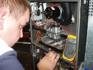 Verifying proper flame signal is imperative for equipment that uses flame rectification. The minimum micro-amp signal should usually not fall below 1.5, and will normally be 3 to 7 micro-amps.
Limit Circuit
The limit circuit is the main protection circuit consisting of a series of switches for the appliance gas valve. Careful inspection and testing of this circuit and its switches is critical for safe operation of the appliance. All of these switches ultimately shut down the gas valve, either directly or through the CPU in the furnace.High Limit Switch:
A normally closed switch wired in series with the low voltage circuit, sometimes wired in the line voltage circuit in series with the transformer, used to protect the heat exchanger from over-heating. This switch must be tested. Usually a bimetal type device that is helical or snap disk, located between the cells in the furnace or above the heat exchanger. It is usually mounted on the back wall of the furnace.If the furnace were cycling on the limit control, you would see the following:
1. The burner would come on.
2. The blower may or may not start.
3. The main burner would go out without the call for heat ending. The blower if running would continue to operate. The induced draft motor if equipped would also continue to run to cool the furnace.
4. The burners would go back on and the blower if running would continue to run.
5. This cycle would continue until the call for heat ends or the power is disconnected.
If the appliance is cycling on the high limit, check for:
1. Plugged or dirty filters.
2. Furnace over-firing (too much gas).
3. Incorrect blower speed.
4. Dirty blower wheel.
5. Plugged air conditioner evaporator coil.
6. Restrictions in airflow (blockage, closed dampers, blocked returns).
7. Equipment oversized for duct system.
8. Other airflow problems.
High Limit Testing (Required Test):
Testing of the high limit requires gradual overheating of the furnace. The preferred method to test the high limit is by blocking off 90 percent of the furnace airflow with a piece of cardboard blocking the return air.Caution: Disconnecting the wires from the blower, or removing the belt, can lead to excessive stresses on the heat exchanger from rapidly overheating the appliance, causing a premature failure of the exchanger.
Every heat exchanger should have a three-part inspection as outlined in RSES publication 630-92 9/86 after a blower motor failure or low airflow problem that has resulted in cycling of the appliance on any limit controls.
Place a temperature probe as close to the limit control as practical. Many times this can be done by removing one screw from the limit and inserting a bead type thermocouple temperature probe near the sensor of the high limit. Set the appliance to call for heat. The limit should trip at the setting shown on the control. For example, L300-30 would mean the limit will open at 300 degrees F shutting off the gas valve, and restart the ignition sequence at 270 degrees F after the furnace has sufficiently cooled.
By ANSI standards, the air temperature in the plenum must not exceed 250 degrees F. Many manufacturers have limit controls that open above this temperature because the limit is located in an area of the furnace that is subject to radiant heat from the heat exchanger, requiring a high setting. The air temperature in the plenum should also be measured to verify that the limit trips below the 250 degree F requirement.
Fusible Link:
A normally closed heat sensitive wire that melts and opens the low voltage circuit to the gas valve. (You cannot visually see that the fusible link has opened. It must be checked with a meter.) Operated on the same principle as a rollout switch, the fusible link has to be replaced in the event of a rollout. (Caution: On some furnaces, operating the burner with the burner door removed can cause the fusible link to fail during service.) If the fusible link were melted, the appliance would not operate; you would read 24 volts across the link with your meter.If the fusible link is open:
1. Make sure all burner shields are in place.
2. Check the heat exchanger for blockage.
3. Check condition of blower wheel in the inducer assembly.
Pressure Switch And Auxiliary Pressure Switch If Required:
A normally open switch used to prove draft on an induced draft furnace. Two-stage furnaces have dual pressure switches, one for high fire and one for low fire. If the furnace were to cycle on the pressure switch, the burners would light, go out, and then the furnace would start the ignition sequence again. This cycle would repeat indefinitely. If the furnace would not prove draft at all, the induced draft motor would continue to run and the ignition sequence would never start.The auxiliary pressure switch is used to sense draft on the secondary heat exchanger. Most of the time, if the auxiliary pressure switch is tripping, the secondary heat exchanger is trapping water.
If the unit is cycling on the pressure switch, check for:
1. Vent pipe blockage.
2. Water in the pressure switch or tube.
3. Leaks in hoses.
4. Blockage in chimney.
5. If 90+ furnace, blockage in intake or exhaust pipe.
6. Induced draft motor amps (as the bearings go bad, the motor slows down and draws excessive current).
7. Secondary heat exchanger drain blockage.
8. Pinched hose or drain line.
Pressure Switch Testing (Required Test):
Install a tee between the pressure switch and the draft inducer motor. Printed on the switch is the actual cutout setting of the switch. Install a digital manometer or Magnehelic® on the branch of the tee. Start the furnace in the heating mode and let it operate until the burners light. Slowly pinch off the tube close to the inducer assembly while watching the pressure on the manometer. The burners should go out when the pressure drops to the setting on the switch.Allow the burners to relight and pull the tube from the switch. The burners should go out and the furnace should not try to re-establish flame.
Spill Switch:
A normally closed manual reset control used to stop the flow of gas to the burners if the stack or fumes are not venting properly. This switch must be tested if the unit is so equipped. The spill switch is found on atmospheric draft appliances and on 80 percent efficient furnaces equipped with a dilution air kit, for venting up a masonry chimney. If the spill switch were tripped, the appliance would not operate; you would read 24 volts across the switch with your meter.If the spill switch is tripped, check for:
1. Chimney or vent blockage.
2. Improper chimney height.
3. Insufficient combustion/ventilation air to provide for proper combustion.
4. Blocked combustion air openings.
5. Air leakage around the return or an open return causing negative space pressure.
6. An attic exhaust fan that is running.
7. A wood burning appliance operating in the house (can create negative pressures).
Perform a ventilation air test as recommended yearly and outlined in the National Fuel Gas Code and International Fuel Gas Code.
Spill Switch Testing (Required Test):
The spill switch is located on the draft hood on older furnaces and on the collection box of some newer furnaces. The spill switch provides protection against a blocked flue by sensing a down draft or back draft condition. The switch location is critical to its operation and it should not be moved or tampered with.All furnaces must prove draft within 5 minutes of establishing a flame. By ANSI standards, the switch must trip with 10 minutes of continuous spilling.
To test the switch, remove the furnace vent from the flue, block the vent with several clean cotton rags or sheet metal, fire the furnace, and allow the unit to spill into the space. Make sure there is adequate ventilation when performing this test as CO could overcome you if the appliance is not functioning properly. A combustion analyzer if so equipped can be used to monitor the CO in ambient air while performing this test; however, many analyzers are not approved as a personal protective device.
The opening temperature of the switch will vary from manufacturer to manufacturer. The switch should open within 10 minutes of operation. This is the maximum time allowed. Many manufacturers have shorter time requirements. If it doesn't open within the time frame required by the manufacturer, replace the switch. The most important thing is that the switch opens by the 10-minute time frame required by the standard.
Rollout Switches:
A normally closed switch located near the burners (manual reset) wired in series with the gas valve low voltage circuit. It usually opens at 180 degrees F to 200 degrees F. Rollout switches are used to stop the flow of gas to the burners if the flame rolls out into the burner compartment impinging on the switch causing an unsafe condition that could lead to a fire. (Caution: Do not ever show the customer where this switch is or how to reset it. If this switch trips, a service technician is needed to find and correct the problem.)If the rollout is tripped, the furnace will not operate; the system blower may start and the inducer motor may operate continually. Most new furnaces will show a flashing light indicating a hard lockout. If the rollout switch were tripped, the appliance would not operate; you would read 24 volts across the switch with your meter.
If the rollout switch is open:
1. Make sure all burner shields are in place.
2. Check the heat exchanger for blockage.
3. Check condition of blower wheel in the inducer assembly.
Perform a ventilation air test as recommended yearly and outlined in the National Fuel Gas Code and International Fuel Gas Code.
Auxiliary Limits (Reverse Airflow):
A normally closed automatic or manual reset switch located near the blower, sometimes two switches, this switch opens if heat is detected near the blower, primarily used on multi-position furnaces and down flow furnace applications. A furnace tripping on an auxiliary limit would act very similar to tripping on the high limit, but will not cycle if it is a manual reset type control. If the auxiliary limit switch were tripped, the appliance would not operate; you would read 24 volts across the switch with your meter.If the auxiliary limit is tripped, check the following:
1. Blower operation.
2. Blower off setting (time or temperature).
3. Blower motor amperage and voltage (motor could be tripping on internal overload).
Some Final Thoughts
Making and interpreting measurements is a crucial part of any job involving service, installation, design verification, engineering, or factory support of HVACR equipment. When it comes to verifying proper operation of the installed equipment, it is critical that measurements made in the field are just as accurate as those made in the laboratory. At Testo we believe that we all have an obligation to assure that the equipment is operating at peak performance levels for the benefit of consumers or end users of HVACR equipment, equipment manufacturers, utilities, the nation's energy future, and the environment.Today, most furnaces, air conditioners, and refrigeration equipment are still being serviced and adjusted with traditional mechanical manometers, fluid analyzers, and manifold gauge sets. Measurement errors can be the result of interpolation errors, calibration errors, poor repeatability of the measurement, and most importantly not having a procedure in place to consistently repeat the measurement process. To rely on measurements, it is imperative that the same results can be obtained by anyone using similar instrumentation.
Digital instrumentation is bridging the gap between the laboratory and the field, allowing technicians to set up equipment to a higher standard than ever before possible. With quality instrumentation, your techs can significantly reduce the error in measurement, reducing callbacks, increasing customer satisfaction, and taking your company to a new level of professionalism. With digital meters, you can spend your time using measurements instead of making and remaking them. The procedures are always easier, and with high quality instrumentation, accuracy can be guaranteed.
James L. Bergmann is an HVAC/R Technical Specialist with Testo Inc. For more information, e-mail jbergmann@testo.com or visit www.testo.com.
Publication date: 12/12/2005
CLICK HERE for Equipment Check Sheet.
Looking for a reprint of this article?
From high-res PDFs to custom plaques, order your copy today!


