Understanding Solenoid Valves
General Information:
Valve Construction And Basic Operation
A solenoid valve is an electronically operated device. It is used to control the flow of liquids or gases in a positive, fully-closed or fully-open mode. The valve is commonly used to replace a manual valve or where remote control is desirable. A solenoid is operated by opening and closing an orifice in a valve body that permits or prevents flow through the valve. The orifice is opened or closed through the use of a plunger that is raised or lowered within a sleeve tube by energizing the coil. The bottom of the plunger contains a compatible sealing material, which closes off the orifice in the body, stopping flow through the valve.The solenoid assembly consists of a coil, plunger, and sleeve assembly. In a normally closed valve, a plunger return spring holds the plunger against the orifice, preventing flow through the valve. When the coil is energized, a magnetic field is produced, raising the plunger and allowing flow through the valve. In a normally open valve, when the coil is energized, the plunger seals off the orifice, stopping flow through the valve.

Direct Operated Solenoid Valves
Direct operated solenoid valves function to directly open or close the main valve orifice, which is the only flow path in the valve. Direct operated valves are used in systems requiring low flow capacities or in applications with low pressure differential across the valve orifice. The sealing surface that opens and closes the main valve orifice is connected to the solenoid plunger. The valve operates from zero pressure differential to maximum rated pressure differential (MOPD) regardless of line pressure. Pressure drop across the valve is not required to hold the valve open.
Pilot Operated Valves
Pilot operated valves are the most widely used solenoid valves. Pilot operated valves utilize system line pressure to open and close the main orifice in the valve body. In a piston-style valve, the main orifice is held closed with a piston seal pressed against the main orifice by the combined fluid pressure and spring pressure. In a normally closed valve, the piston is shifted or opened when the pilot operator is energized. This allows fluid behind the piston to evacuate through the valve outlet. At this point, the system line pressure moves the piston, opening the main orifice of the valve allowing high capacity flow through the valve. When energizing the coil of a normally open valve, fluid pressure builds up behind the piston, forcing the piston to seal the main orifice of the valve.

Design Terminology
Solenoid Valve Applications:
Evaporator Temperature Control
A solenoid valve installed in the liquid line as close to the evaporator as possible, in conjunction with a narrow differential thermostat, is an excellent temperature control. By mounting the thermostat bulb in the supply or discharge air across the evaporator, the temperature swing is limited only by the differential of the thermostat.

This type of temperature control can be used on a single or multiple evaporator system and is particularly useful on multiplexed systems with evaporators at different temperatures.
Defrost Pump Down
In situations where the condensing unit is installed in a low ambient, such as on a rooftop in northern climates, and the evaporator is operating at a temperature above the ambient, a pump down solenoid valve should be used. This allows the pressure control to be set at a cut out of 1 to 2 psi and the cut in to be set at a pressure below the pressure corresponding to the ambient temperature. This will ensure that the condensing unit will start after cooling down during the defrost.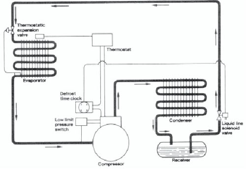
When a system has a defrost pump down solenoid valve, a thermostat should be used in series with the defrost time clock to control the temperature of the space or fixture. An alternative to the thermostat would be an evaporator pressure regulator.
Note: System diagrams are for illustrative purposes and are intended to show application of solenoid valves only.
Heat Reclaim Systems
Basically, there are two types of heat reclaim systems: the series system and the parallel system.In the series system, during normal operation, the discharge gas is condensed completely in the condenser. During the heating mode, the normally opened solenoid valve closes off the condenser and the normally closed solenoid opens to allow the discharge gas to flow into the heat reclaim coil. Complete condensation can occur in the heat reclaim coil if so designed, but manufacturers often prefer to take advantage of all the sensible heat available but only part of the latent heat, depending on the condenser for complete condensation.

In the parallel systems there are, in effect, two separate condensers. During normal operation, the condenser is used for complete condensation of the discharge gas. In the heat reclaim mode the discharge gas is completely condensed in the heat reclaim coil, thus maximizing the use of both sensible and latent heat. Some manufacturers recommend installing a 1/4-inch line from the heat reclaim coil, at its lowest point, back to the receiver to ensure the proper drainage of oil and liquid refrigerant during the off cycle. Other manufacturers suggest the installation of a pressure control, to ensure that the system will switch from the heat reclaim mode to the condenser in the event of fan stoppage or clogged filters.

Split Evaporator — Humidity Control
There are often times when the air temperature is satisfactory but the humidity level is too high. This can be remedied by using only half the evaporator to dehumidify the air without excessive cooling and the addition of auxiliary heat. This can best be accomplished by using a normally open solenoid valve on one half of the evaporator controlled by a humidistat.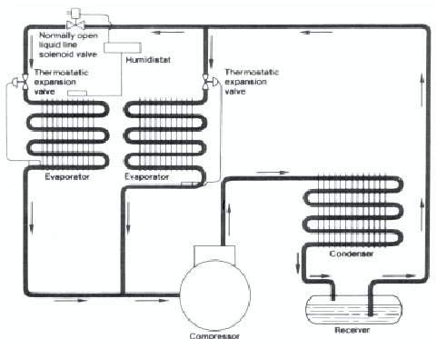
Hot Gas Defrost System
Hot gas defrost offers an excellent alternative to electric or air defrost. In this system the hot compressor discharge gas is routed to the outlet of the evaporator. This hot gas warms the evaporator, thaws any frost that has accumulated, condenses into a liquid, and flows into the common liquid line to feed the other evaporators.In order for this system to work properly, check valves must be installed to allow flow around the expansion valves. A pressure reducing valve should be used in the liquid line to provide a pressure differential between the condensed refrigerant leaving the defrosting evaporator and the common liquid line.
The system shown is drawn with only two evaporators but it is recommended that only 25 percent of any multiplexed system be hot gas defrosted at any given time.
An alternative to the hot gas defrost system is the cool gas defrost, which uses the gas from the top of the receiver to defrost the evaporators. Because the cool gas defrost operates at a lower temperature, the thermal expansion of the refrigeration lines is reduced. This often eliminates the need for special piping techniques and leaks caused at line connections by excessive thermal flexing.

Capacity Control System
A simple method of providing compressor unloading is to use a solenoid valve connecting the discharge and suction lines of the compressor. The solenoid valve is controlled by a pressure control which responds to suction pressure. When the switch closes, it opens the normally closed solenoid valve and discharge gas is short circuited back to the suction side of the compressor.In order to prevent overheating of the compressor, a thermostatic expansion valve should be installed to provide cooling to the compressor suction gas. An alternative method consists of injecting hot gas into the evaporator inlet. This prevents overheating of the compressor and increases the velocity of the gas through the evaporator.
This type of unloading should not be attempted without thorough analysis of solenoid valve and expansion valve sizing.

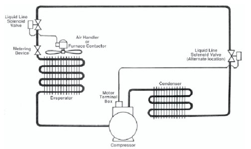
Liquid Line Shut-Off
In an effort to obtain a higher efficiency rating on residential and commercial air conditioning systems, a normally closed solenoid valve typically is installed in the liquid line located near the air handler or furnace. In this case, the solenoid valve is wired in parallel with the contactor circuit (24 VAC) and may require a larger transformer to accommodate the valve.As an alternative method, a normally closed solenoid valve may be located in the liquid line near the condensing unit and wired directly to the compressor motor terminal box. This solution improves system efficiency and maintains the refrigerant charge in the condenser coil during the off-cycle of the compressor which prevents refrigerant migration when long piping runs are used.
If the application requires a fail-safe or open mode, a normally open solenoid valve may be used. In this instance, the valve may also be located in the condensing unit and wired in series with the compressor crankcase heater.
Compiled by the Parker Hannifin Corporation Engineering Staff, New Britain, Conn. For more information, visit www.parker.com/skinner/rseries.
Publication date: 07/28/2003
Looking for quick answers on air conditioning, heating and refrigeration topics? Try Ask ACHR NEWS, our new smart AI search tool. Ask ACHR NEWS
Looking for a reprint of this article?
From high-res PDFs to custom plaques, order your copy today!


