Selecting, Installing Oil Separators
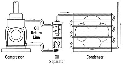
Oil separators remove oil from the compressor's discharge gas, temporarily store the oil, and then return it to the compressor's crankcase. Oil separators are located close to the compressor in the discharge line. (See Figure 1.) Even though most oil separators are designed to be mounted vertically, there are some horizontal models available on the market.
Oil separators are essential on low or ultra-low temperature refrigeration systems and on large air conditioning systems up to 150 tons. Most compressor manufacturers require oil separators on all two-stage compressors. Oil separators can also act as discharge mufflers to quiet compressor pulsation and vibration noises.
Unusual system operating conditions often occur to compressors and rapid removal of oil from the compressor's crankcase happens. System flooding is an example.
Sometimes these occurrences happen beyond the control of both the designer and installer. The velocity of the refrigerant flowing through the system should return oil to the compressor's crankcase. Even though proper refrigerant system piping designs maintain enough refrigerant velocity to ensure good oil return, sometimes this added pressure drop, which assists in getting the right refrigerant velocity for oil return, hampers the system's efficiencies.
Sometimes a higher than normal pressure drop is intentionally designed into a system for better oil return. This, however, will cause higher compression ratios and low volumetric efficiencies that will lead to lower system capacities.

Detrimental Effects Of Oil In A System
Oil that gets past the compressor and into the system not only robs the compressor crankcase of vital lubrication, it coats the walls of the condenser and evaporator. Oil film on the walls of these important heat exchangers will reduce their heat transfer abilities. The condenser will not be able to reject heat as efficiently as it should. Even though this oil film in the condenser will be hotter and thinner than if it were in the evaporator, system efficiencies will suffer. Head pressures will rise, causing higher compression ratios and lower volumetric efficiencies with lower than normal system capacities.Oil that coats the walls of the evaporator will decrease heat transfer to the refrigerant in the evaporator. A film of oil bubbles, which acts as a very good insulator, will form on the inside of the evaporator. The evaporator will now see a reduced heat load that will cause the suction pressure to be lower. Lower suction pressures cause higher compression ratios and lower volumetric efficiencies. The result is lower system capacity with much longer running times.
Most control valves, including TXV and capillary tubes, will also experience inefficient performance due to the pressure of oil filming. Capillary tubes may experience wide variation in flow rates. Usually, reduced refrigerant flow rates with higher head pressures and lower suction pressures are experienced. TXV remote bulbs may not sense the correct refrigerant temperature at the evaporator outlet, causing improper superheat control. TXV hunting can also occur.
Looking for quick answers on air conditioning, heating and refrigeration topics? Try Ask ACHR NEWS, our new smart AI search tool. Ask ACHR NEWS
If an oil separator isn't employed, the compressor often sees slugs of oil that are returning from the evaporator. The compressor's pistons can momentarily pump slugs of liquid oil that can build tremendous hydraulic forces because of the incompressibility of most liquids. Serious compressor valve and drive gear damage can result.
How Oil Separators Work
Oil separators are almost always made of steel. As oil-laden discharge gas enters the oil separator's very large internal volume, it immediately slows down its velocity. This low velocity is the key to good oil separation. The oil is mixed with the discharge gas in the form of a fog. This refrigerant/oil fog now runs into internal baffling, which forces the fog mixture to change direction. At the same time, this fog mixture is slowing down rapidly on the surface of these baffles. Very fine oil particles collide with one another and form heavier particles. Finally, fine mesh screens separate the oil and refrigerant even farther, causing larger oil droplets to form and drop to the bottom of the separator. Often, a magnet is connected to the bottom of the oil sump to collect any metallic particles. When the level of oil gets high enough to raise a float, an oil return needle is opened and the oil is returned to the compressor crankcase through a small return line connected to the compressor crankcase. The pressure difference between the high and low sides of the refrigeration or air conditioning system is the driving force for the oil to travel from the oil separator to the crankcase.The oil separator is in the high side of the system and the compressor crankcase in the low side. This float-operated oil return needle valve is located high enough in the oil sump to allow clean oil to be automatically returned to the crankcase. Only a small amount of oil is needed to actuate the float mechanism. This ensures that only a small amount of oil is ever absent from the crankcase at any one given time. When the oil level in the sump of the oil separator drops to a certain level, the float will force the needle valve closed.
The oil return line from the oil separator to the crankcase should be just above room (ambient) temperature. This is caused from heat conduction to the line from the hot oil separator. If the oil return line is cool or cold to the touch, there may be liquid refrigerant vaporizing in it as it passes oil. This problem can result from the oil separator's shell being uninsulated or poorly insulated and becoming too cool. If the shell is too cool, it can cool discharge gasses too much, resulting in condensed (liquid) refrigerant in the bottom of the oil separator. This will cause the float to rise too often because of increased levels of an oil and liquid refrigerant mixture in the bottom of the separator.
Once the float rises and the orifice opens, the mixture of liquid refrigerant and oil passes through the oil return line. The liquid refrigerant will vaporize from the sudden pressure drop and cause the cool temperatures in the return line.
Helical Oil Separators
Helical oil separators offer 99 percent to 100 percent efficiency in oil separation with low pressure drop. Upon entering the oil separator, refrigerant gas and oil fog mixture encounters the leading edge of a helical flighting. (See Figure 2.) The gas/oil mixture is centrifugally forced along the spiral path of the helix, causing the heavier oil particles to spin to the perimeter, where impingement with a screen layer occurs. This screen layer serves as an oil stripping and draining medium. The separated oil now flows downward along the boundary of the shell through a baffle and into an oil collection area at the bottom of the separator.The specially designed baffle insulates the oil collection and eliminates oil re-entrainment by preventing turbulence. Virtually oil-free refrigerant gas exits the separator through a fitting just below the lower edge of the helical flighting. A float-activated oil return valve allows the captured oil to return to the crankcase or oil reservoir.
Selecting An Oil Separator
Although oil separator catalogs show capacity in tons or horsepower, the actual tonnage or Btu capacity may vary widely from the horsepower size of the compressor. Actual capacity of compressors is dependent on suction pressures, discharge pressures, liquid temperatures, rpm, and the density of the suction gases.The larger the capacity of the compressor, the larger the separator's volume must be, regardless of the piping size connections of the separator. The separator must be large enough to match the compressor, and the connection sizes must be the same, or larger, than the discharge line size of the system. This allows the discharge gases in the separator to be near the same pressure as the discharge line because of minimal pressure drop within the oil separator. Do not ever undersize an oil separator. It will lose its ability to return oil and will cause high pressure drop, causing system inefficiencies.
When adding an oil separator to an existing system, care must be taken to check the system frequently after start-up. Literally gallons of oil may be trapped in a system and may gradually return to the compressor crankcase and overfill it.
Installing An Oil Separator
The oil separator should be rigidly supported by a solid surface. It should never be supported by the discharge line alone. Its own weight plus the weight of the oil in the separator will stress the discharge line and may cause failure. A vibration eliminator should always be installed in the discharge line before the oil separator.The separator should then be supported rigidly to a solid surface such as a concrete wall or floor, steel post, or to the same base as the compressor. Simple lead anchors and bolts are not good for vibrating equipment because they usually work themselves loose. Studs should be anchored in the floor when it is poured. Special anchors guaranteed and designed to handle vibration should be used on an existing floor.
On new installations, the compressor and separator should be mounted in their final position, and then the interconnecting piping installed while making sure alignment is perfect. There should not be any long, vertical discharge line. If there is a vertical discharge line of more than 10 to 12 feet, it is a good practice to install a drop leg trap to the floor just before the riser. This will catch any oil left in the vertical discharge line and prevent it from draining back to the compressor's discharge.
The oil return line, which runs from the oil separator to the crankcase, is usually 3/8 SAE flare. Sometimes, there is a chance that there may be some liquid refrigerant that condensed in the separator during the off cycle. You do not want to return this mixture directly back to the crankcase. Or, if the float and needle assembly in the separator are stuck open, hot gas would blow back directly into the crankcase and cause severe overheating of the oil. In the case of the semi-hermetic compressor, oil normally returns to the compressor with the suction gas through the end bell of the compressor. This gas has to flow through the motor compartment and through an oil return check valve in the crankcase.
This will help vaporize any condensed refrigerant in the oil before it reaches the crankcase. The tap on the compressor's suction housing makes an excellent return point for oil coming from an oil separator. Any liquid refrigerant mixed with the oil will be vaporized by the motor heat. Any hot gas blown back will be mixed with cool suction gas and stands a better chance of not harming the compressor if an oil fill hole is used directly to the crankcase.
Some oil separator manufacturers can provide a wraparound heater of about 50 watts to help prevent refrigerant condensing in the coil separator during the off-cycle. Most oil separators must be insulated to keep them hot during the on and off cycles. This will prevent refrigerant from condensing in them and mixing with the oil in their sumps.
John Tomczyk is a professor of HVACR at Ferris State University, Big Rapids, MI, and the author of Troubleshooting and Servicing Modern Air Conditioning & Refrigeration Systems, published by ESCO Press. To order, call 800-726-9696. Tomczyk can be reached by e-mail at tomczykj@tucker-usa.com.
Publication date: 11/03/2003
Looking for a reprint of this article?
From high-res PDFs to custom plaques, order your copy today!


