Six Steps For Ice Maker Diagnostics
Refrigeration components will react and try to compensate for nonrefrigeration-component problems. By following this procedure step by step, problems that affect the refrigeration sequence can be identified without needlessly changing components.
Each step involves checking several items before proceeding to the next step. Follow each step carefully; the problem may be identified prior to the completion of all six steps.
Step 6 requires the use of information gathered in the previous steps. Therefore, write down information as you collect it and record it on the proper refrigeration component diagnostic chart.
Note: Do not make adjustments or turn the machine off until you have identified the malfunction. The problem may not repeat itself.
Step One: Visual Inspection
Talk to the ice machine user to identify the perceived problem(s). The user’s information could help point you in the right direction initially, and may be a determining factor in your final diagnosis.Here are a few questions to consider asking the user:
Here are some possible problems and corrective measures:
Note: If you make any of these corrections, be careful not to interfere with the ice production inspection.
Step Two: Ice Production
The amount of ice a machine produces is in direct relationship to water and air temperatures. An ice machine produces more ice in a 70 degree F room with 50 degree water than in a 90 degree room with 70 degree water.Use the following list to check ice production. Make sure the water curtain is in place to ensure no water is being lost while checking ice production.
Operation conditions:
1. Condenser inlet air temperature.
2. Water inlet temperature (entering sump trough).
3. The published 24-hour ice production at the above conditions (in lbs/24 hours).
Ice production check:
1. Freeze time plus harvest time = total cycle time.
2. 1,440 divided by total cycle time = cycles/day.
3. Weight of one harvest times cycles/day = lbs/24 hours.
Note: To use the 24-hour ice production formulas, time must be in minutes and weight of ice in pounds (lbs).
Times are in minutes. For example: 1 minute, 15 seconds; convert to 1.25 minutes; 15 seconds divided by 60 seconds = 0.25 minutes.
Weights are in pounds. For example: 9 lbs, 4 oz.; covert to 9.25 lbs; 4 oz divided by 16 oz = 0.25 lbs.
Compare your findings in the ice production check to published specifications in operating conditions. Record your findings on the refrigeration diagnostic chart.
If the ice production is OK, determine if another ice machine is needed, if more storage capacity is needed, or if moving the existing equipment to lower load conditions will meet the customer’s needs.
If the ice production is low, record your findings on the refrigeration diagnostic chart and continue troubleshooting.
Step Three: Ice Fill Pattern
Fill patterns on the evaporator are normal when the thickness is a uniform 1/8 inch from top to bottom and side to side. (The ice bridge is the interconnecting waffle between the cubes.) The water should freeze on the entire evaporator at the same time. Ice forming on the bottom of an evaporator then working its way up to the top is not normal and must be noted as “thin on top and thick on bottom.”Important: The water curtain must be in place to ensure no water is being lost while checking the fill pattern.
Examples of ice fill patterns:
Record your findings for fill patterns on the refrigeration diagnostic chart.
Step Four: Water System
Water-related problems in ice machines often have the same symptoms as refrigeration system malfunctions.Water area failures must be identified and eliminated prior to changing refrigeration components. An example is a water dump valve leaking during the freeze cycle or starving the TXV. The characteristics of both failures are similar.
Here are some possible problems and corrective measures:
Problem: Water area (evaporator) dirty. Remedy: Clean.
Problem: Water inlet pressure not between 20 to 80 psi or that specified by manufacturer. Remedy: Install water regulator valve or increase water pressure.
Problem: Incoming water supply temperature must be 35 degrees to 90 degrees or that specified by manufacturer. Remedy: Too hot — check hot water line; check valves in the other store equipment.
Problem: Water filter (if used) restricted. Remedy: Replace filter.
Problem: Dump valve malfunctioning. Remedy: Clean dump valve. Re-place as needed.
Problem: Vent tube not installed on water outlet drain. Remedy: See installation instructions.
Problem: Water trough hoses leaking water. Remedy: Install properly or replace.
Problem: Water inlet valve stuck open. Remedy: Clean or replace.
Problem: Water freezing behind evaporators. Remedy: Check water flow.
Problem: Water freezing between plastic extrusions and evaporators. Remedy: Tighten or replace extrusion/gaskets.
Problem: Water flow uneven across evaporator(s). Remedy: Clean ice machine. Check water flow rate.
Step Five: Refrigeration
The refrigeration section requires taking several checks to gather information.Note: Only proceed to Step 5 after Steps 1 through 4 have been thoroughly checked and a final diagnosis could not be determined.
5A: Analyze discharge pressure.
Using the operational pressure chart, determine if the discharge pressure is correct for the ambient temperature surrounding the ice machine.
If the discharge pressure is high, eliminate possible problems in the order listed in the following section and follow appropriate corrective measures.
Here are some possible problems and corrective measures:
Problem: Excessive load conditions (air/water temperatures). Remedy: Relocate ice machine to location within guidelines of installation instructions.
Problem: Dirty condenser. Remedy: Clean.
Problem: Water regulating valve (water-cooled condenser): Supply water line is too small. Remedy: Replace with proper size line.
Problem: Water regulating valve (water-cooled condenser): Out of adjustment. Remedy: Readjust.
Problem: Water regulating valve (water-cooled condenser): Defective regulating valve. Remedy: Replace.
Problem: Water regulating valve (water-cooled condenser): Dirty (scaled). Remedy: Clean.
Problem: Fan motor/fan cycling switch defective (air-cooled models). Remedy: Diagnosis control. Replace if necessary.
Problem: Restriction in highside lines. Remedy: Repair; see evacuation/charging procedures.
Problem: Headmaster control valve defective (remote machines). Remedy: Refer to Headmaster control valve diagnostics.
Problem: Improper refrigerant charge. Remedy: Refer to evacuation charging procedures.
Problem: Noncondensibles in system. Remedy: Refer to evacuation charging procedures.
If the discharge pressure is low, you need to eliminate possible problems in order listed on chart and follow appropriate corrective measures.
Problem: Load conditions low (air/water temperatures). Remedy: Relocate ice machine to location within guidelines of installation instructions.
Problem: Water regulating valve (water-cooled condenser): Out of adjustment. Remedy: Readjust.
Problem: Water regulating valve (water-cooled condenser): Leaking water during harvest cycle. Remedy: Readjust/replace if necessary.
Problem: Water regulating valve (water-cooled condenser): Defective. Remedy: Replace.
Problem: Water regulating valve (water-cooled condenser): Defective regulating valve. Remedy: Replace.
Problem: Fan motor/fan cycling switch defective (air-cooled models). Remedy: Diagnose control, replace if necessary.
Problem: Headmaster control valve defective (remote machines). Remedy: Refer to Headmaster control valve diagnostics.
Problem: Low refrigerant charge. Continue through six-step procedures.
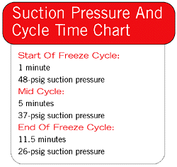
5B: Analyze suction pressure.
Note: Discharge pressure must be analyzed before suction pressure. To analyze suction pressure, compare the Suction Pressure and Cycle Time Chart for the particular ice machine on which you are working. The suction pressure gradually drops as ice forms throughout the freeze cycle.
For normal suction pressure, proceed through the six-step procedure. For low or high suction pressure, refer to the manufacturer’s suction pressure low and high charts.
By comparing the figures, you can determine if suction pressure is properly pulled down. Develop such a chart as Table 1 and you will see where the suction pressure should be compared to the amount of time the ice machine is into the freeze cycle.
Note: If the ice machine is located in other than 90 degree air and 70 degree water, another chart must be developed for comparison purposes.
If suction pressure is high, you need to eliminate the possible problems in the order listed here and follow appropriate correction measures.
Problem: High discharge pressure affecting low side. Correction: Refer to discharge pressure high chart.
Problem: Hot gas valve stuck open. Correction: Replace valve.
Problem: TXV flooding. Correction: Continue through six-step procedure.
Problem: Inefficient compressor. (Do not perform pumpdown test.) Continue through six-step procedure.
Problem: Harvest pressure-regulating solenoid valve leaking (remote machines). Correction: Replace valve.
If suction pressure is low, eliminate the possible problems in the order listed and follow appropriate corrective measures.
Problem: Low load conditions. Correction: Verify that water pump is operating.
Problem: Water area problem. Correction: Refer back to Step 4.
Problem: Plugged drier/restriction in liquid line. Correction: Repair; refer to evacuation/charging procedures.
Problem: TXV starving/low on charge. Continue through six-step procedure.
5C: Hot gas valve check.
Here are some possible problems:
Check procedures — Note: On dual expansion valve ice machines, procedures must be performed twice, once for each hot gas valve.
First, feel the hot gas valve inlet after five minutes into freeze cycle. (Caution: The hot gas valve inlet could be hot enough to burn your hand. Touch it briefly.)
Second, determine if the inlet of the hot gas valve is hot or close to the compressor discharge line temperature. With a leaking hot gas valve, the inlet temperature remains close to the discharge line temperature (to the touch) during the freeze cycle.
Record your findings on the refrigeration component diagnostic chart.
5D: Discharge line temperature.
Knowing if the discharge line temperature is increasing, decreasing, or remaining constant can be important diagnostically. Maximum compressor discharge line temperature on a normally operating ice machine steadily increases throughout the freeze cycle. Comparing the temperatures over several cycles results in a consistent maximum discharge line temperature.
Ambient air temperatures affect the maximum discharge line temperature. Higher ambient air temperatures at the condenser equals higher discharge line temperatures at the compressor. Lower ambient air temperatures at the condenser equals lower discharge line temperatures at the compressor.
Regardless of ambient temperature, the freeze cycle discharge line temperature will be higher than 160 degrees on a normally operating ice machine.
Procedure:
1. Connect a temperature probe on the compressor discharge line within 6 inches of the compressor and insulate.
2. Observe the discharge line temperature for the last three minutes of the freeze cycle; record the maximum discharge line temperature.
If the discharge line temperature is above 160 degrees at end of freeze cycle — Ice machines that are operating normally have consistent maximum discharge line temperatures above 160 degrees.
If the discharge line temperature is below 160 degrees at end of freeze cycle — Ice machines that have a flooding expansion valve have a maximum discharge line temperature that decreases each cycle.
Verify that the expansion valve sensing bulb is 100 percent insulated and sealed airtight. Condenser air contacting an incorrectly insulated sensing bulb will cause overfeeding of the expansion valve. Also, verify that the expansion valve’s sensing bulb is positioned and secured correctly.
5E: Compressor.
Suction valves — An inefficient compressor can be hard to detect. Components or problems that are not directly related to the compressor can simulate a faulty compressor.
To diagnose a faulty compressor, systematically check other components and rule them out one by one, following the six-step procedure. Step 6 will then indicate if a compressor change is needed.
Symptoms of an inefficient compressor:
Note: An inefficient compressor may pump down and hold. Therefore, this type of test must not be used as a determining factor for replacing compressors.
Discharge valve —
Step Six: Final Analysis
Thoroughly following the first five steps eliminates all nonrefrigerant problems. The Refrigeration Component Chart will verify what is causing the problem. Fill out the chart thus:Rens is service publications manager for Manitowoc Ice Inc., Manitowoc, Wis.; 800-545-5720.
Publication date: 07/07/2003
Looking for quick answers on air conditioning, heating and refrigeration topics? Try Ask ACHR NEWS, our new smart AI search tool. Ask ACHR NEWS
Looking for a reprint of this article?
From high-res PDFs to custom plaques, order your copy today!


