Btu Buddy 12: Tackling Low Airflow With Electric Heat
In this edition of the Btu Buddy series, Bob gets a call from the dispatcher about an office that has electric heat. It is very cold outside and one of the office zones is not heating as it should. It is 62 degrees F in that zone.
Bob arrives and finds the zone temperature is now about 60 degrees F, and the personnel are very uncomfortable. Small electric space heaters have been brought in to spot heat the zone that is so cold.
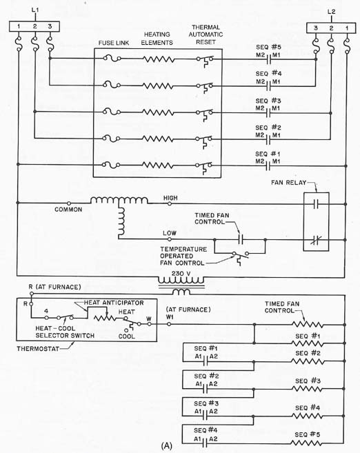
Bob goes to the equipment room and finds a blueprint of the building and discovers there are about 10 electric heaters that have a wiring diagram like that of Figure 1. Each zone has an air handler, so they are all the same.
Bob goes to the air handler for the zone that has the problem. It is above the ceiling, so he sets up a ladder. There is a light bulb next to the air handler, so there is plenty of light. He can hear the fan running and the duct seems to be hot, so something is working. All looks well, so he is standing on the ladder looking bewildered when Btu Buddy appears and asks, "What is the problem?"
Bob says, "There are so many wires in this panel that I don't know where to start."
Btu Buddy says, "Let's do it like all problems; see what we know, then explore what we don't know and find out what that is. First identify the low voltage circuits entering. It is that terminal block that is isolated from the rest. Remember low voltage must be isolated from high voltage. Now, identify the high voltage terminals that connect directly to the heater circuits. Now, take your ammeter and check the amperage to each heater."
Bob takes an amperage reading at each heater. He discovers that some have current flow and some do not. Maybe this is why there is not enough heat, he says.
Btu Buddy suggests, "Bob, take the amperage at both sides of each electric heat strip. Make a drawing of what the amperage is at each place."
Looking for quick answers on air conditioning, heating and refrigeration topics? Try Ask ACHR NEWS, our new smart AI search tool. Ask ACHR NEWS
There are five heat strips that are 5 kW each, so Bob takes 10 readings. The voltage is 230 volts. The amperage should be about 22 amps at each place (5,000 watts/230 volts = 21.7 amps). The results look like this from the top to the bottom using Figure 1.
First heater is 22 amps on the left and 22 amps on the right.
Second heater is 18 amps on the left and 0 amps on the right.
Third heater is 0 amps on the left and 0 amps on the right.
Fourth heater is 22 amps on the left and 22 amps on the right.
Fifth heater is 0 amps on the left and 15 amps on the right.
Bob looks at the readings and says, "Now I am more confused than ever. What is going on here?"
Btu Buddy says, "This will all add up in a minute. We will get to the bottom of it."
Bob says, "I do not see how a heater can be drawing current on one side and not the other."
"Just wait and see," Btu Buddy says.
"What do we do next," Bob asks.
"Let's start by pulling the heater section out of the furnace," Btu Buddy suggests.
Bob shuts off the power and locks out the power supply, and with the key in his pocket, he feels confident.
Btu Buddy says, "Before you put your hand in that electrical panel, check the voltage. Fasten one lead to a ground and touch your other meter lead to all of the terminals and look for any signs of voltage."
"With the power off, why does this need to be done?" asks Bob.
"It is the safe thing to do. There have been cases of circuits from other sources that have been run into a panel and you do not want to find this out the hard way," Btu Buddy says.
Bob checks all circuits to ground and finds the panel safe to work in.
Checking Out The Heater Section
Bob loosens the power wiring so that he can pull the heater section out. Then he disconnects the low voltage power supply. He then pulls the entire heater section out and lays it on the floor for an examination.Bob says, "This heater was really hot at one time. Look at the elements. Some of them have burned in two and are touching the frame."
Btu Buddy says, "Get your diagram of the heaters with the amperage results you recorded, and list beside each heater what you see."
The following is what Bob noted:
First heater is 22 amps on the left and 22 amps on the right. This heater looks good.
Second heater is 18 amps on the left and 0 amps on the right. The heater coil is burned in two and one side is touching the frame.
Third heater is 0 amps on the left and 0 amps on the right. This heater has a burned fuse link.
Fourth heater is 22 amps on the left and 22 amps on the right. This heater looks good.
Fifth heater is 0 amps on the left and 15 amps on the right. The heating element is burned in two and one side is touching the frame.

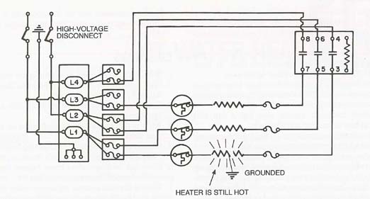
Bob says, "I can understand why the number 3 heater is not drawing current. It needs a new fuse link (see Figure 2). But I do not understand heaters 2 and 5. Why are they drawing current on one side only?"
Btu Buddy explains, "There is still power to the heating elements on both sides. The coil is burned in two. One side is suspended in air, the other is touching the frame and has about 115 volts across that part of the coil (see Figure 3)."
"Well, now I need to go to the supply house for parts," says Bob.
"What are you going to get?" asks Btu Buddy.
"I need two heating elements for this specific heater and a fuse link," Bob says.
Btu Buddy suggests, "Check the continuity across the automatic reset thermal controls on the units that were not working, just in case one of them has malfunctioned."
Bob does this and finds that one of them indeed has an open circuit. He finds the rest to be good.
Bob picks up the parts he needs, arrives back at the job, and installs the new heating elements, automatic reset thermal control, and fusible link. He is ready to put the system back in operation when Btu Buddy asks, "What do you think happened to this system?"
Bob says, "I have no idea. It probably just burned up."
Btu Buddy says, "You can do better than that. Did you see any signs of problems?"
"Well, the system looked like it had been hot. Maybe it had been operating with too little airflow," Bob says.
Btu Buddy suggests, "It would be a good idea to check that out when you start the system."
At Btu Buddy's suggestion, Bob locates a temperature tester lead downstream of the heating elements before he starts the system.
Bob starts the system and checks the amperage at each heater, and they are all operating. All seems well, except the outlet air temperature seems to be too high. It is running 150 degrees F.
Btu Buddy recommends to Bob that he peak inside the duct and look at the elements while in operation. Bob looks and they are glowing red hot. Btu Buddy says, "Shut the system off."
Bob shuts off the system and asks, "Why?"
Btu Buddy says, "These elements are not meant to glow red hot. There is not enough airflow across them for some reason, and they are going to burn out again. It is not worth taking the risk of letting them run."
"Well, what do we do?" asks Bob.
Btu Buddy says, "Let's look for a restriction in the airflow."
Bob takes the panel off of the air handler and looks at the fan and the air conditioning coil. It now becomes obvious what the problem is. The coil is matted with dirt on the inlet side.
Bob asks, "Now what do we do? It would really be a problem to clean this coil above the ceiling with detergent and water."
Btu Buddy says, "Look at the fan wheel. It is really packed with dirt. This system must be cleaned before it is put back in operation. Notice that the fan is after the coil. If the fan wheel is this dirty, you can imagine what the inside of the coil must look like because the dirt on the fan wheel is what came through the coil. This probably happened during the summer when the coil was wet. This job must be done correctly or there will be problems in the near future."
Cleaning The Fan Wheel And Coil
Bob gets set up by shutting off the electrical power and locking it down. He then removes the fan wheel. He carries it outside and sprays detergent on it to let it soak. He has to place it in a parking garage to keep it from freezing.Bob then goes back in and spreads plastic on the suspended ceiling under the fancoil unit. Bob cleans the entire matted surface from the coil inlet to prevent this from having to go down the drain. He then uses a pump-type sprayer and sprays the coil with an approved coil cleaning liquid, paying close attention to getting the center of the coil wet. He sprays both the front and the back of the coil. He then goes to the outside to clean the fan while the coil soaks. The fan wheel cleans up easy with the detergent.
Bob installs the fan wheel after giving the coil another soaking. He then uses a pressure washer to clean the coil. He says, "I can't believe all of the dirt coming off the coil. There must be a problem with the filtering system on this unit."
Btu Buddy says, "Now you are thinking Bob. When you get it cleaned up, we will look for the ‘why' of what happened."
Bob had to really watch the condensate drain line that was draining off all of the water and detergent to make sure it didn't overflow, even though the system had a secondary drain pan.
With the coil clean and the fan wheel cleaned and back in place, Bob started the fan only and let it run for a few minutes to prevent water from blowing into the electric heat coils. Then he turned on the electric heat and measured the air temperature with all of the heat running. The air temperature was running at 115 degrees F. All seemed to be well.
Btu Buddy then says, "Let's get to the root of this problem and see why that coil was so dirty."
Bob removes the filter and it is dirty, but not plugged completely. There is a lot of dust in the return air duct that seems out of the ordinary. He goes to the conditioned space where the return air is entering the system.
"I see what the problem is," says Btu Buddy. "What do you see, Bob?"
Bob says, "Boy, I don't know. There seems to be a lot of dust in this room but I can't imagine why."
Btu Buddy says, "This is the mail opening room. A lot of dust is created by mail, but an extra amount is created when the mail is opened. Notice there is also a shredder. That also creates a lot of dust."
Bob asks, "Why doesn't the filter remove that dust from the air?"
Btu Buddy explains, "Typical media filters are not that efficient, some people say about 5 percent. They pick up large objects but not much fine dust. So most of the fine dust, such as in a mail room, will go right through. It takes a while, but eventually enough dust will lodge in the coil, especially during the cooling season when the coil is wet, to restrict the airflow."
"Well," Bob says, "another new experience. Does it ever end?"
"Lets hope not," notes Btu Buddy, "this is what keeps this profession interesting, all the new experiences. My granddad from Alabama used to say that everyday is like knots on a pine log; each day like the pine log has a different pattern."
Btu Buddy continues, "Bob, you did a good job on this. I think you should explain the situation of the high dust level to the management here, and recommend that a higher density filter be installed and that a routine maintenance contract be established to keep all of the systems in this building in good shape."
Bob came back after talking to the building manager with a big smile. The manager had asked for a quote for the contract and assured Bob that he would take it.
Btu Buddy comments, "Now see, you have brought your company some more business. You are becoming more valuable each day to them. Service contracts are great because you can work them on ‘off days' when there are no service calls. It provides a set amount of revenue that the company can rely on each month and year. Great job, Bob."
Bob then asks a question, "How do all of those thermal overloads work together with the fuses to make a system reliable?"
Btu Buddy says, "Meet me for lunch tomorrow with a pad and a diagram of a system and we will discuss it in detail. You must understand the entire system, not just one or two controls. They must all work together."
Bill Johnson has been active in the HVACR industry since the 1950s. He graduated in gas fuel technology and refrigeration from the Southern Technical Institute, a branch of Georgia Tech (now known as Southern Polytechnic Institute). He taught HVAC classes at Coosa Valley Vocational & Technical Institute for four years. He moved on to become service manager for Layne Trane, Charlotte, N.C. He taught for 15 years at Central Piedmont Community College, part of this time as program director. He had his own business for five years doing installation and service work. Now retired, he is the author of Practical Heating Technology and Practical Cooling Technology, and continues as a co-author of Refrigeration & Air Conditioning Technology, 5th Edition, all published by Delmar Publishers. For more information, he can be reached at 704-553-0087, 704-643-3928 (fax), or bmj@myexcel.com.
Publication date: 03/22/2004
Looking for a reprint of this article?
From high-res PDFs to custom plaques, order your copy today!


