Installation, Maintenance of HVAC Coils Explained
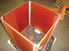
This custom-designed copper/copper replacement coil is
headed for an off-shore application.
There are cases in which the best option for the customer includes changing a system’s direct expansion (DX) coils. This article includes guidelines to do the job efficiently and correctly, but remember: It’s not a substitute for other established procedures. However, following these methods may help prevent you from making some common (and some not-so-common) mistakes.
First of all, it’s very important to remember that the manifold assembly is not a handle. Using the manifold as a lifting point will probably result in a tube fracture at the header plate. Take time and please, use proper rigging techniques to position the coil.
The replacement coil should slide freely into the existing coil opening.
COILS, FITTINGS, AND FINS
Depending on the application, most DX cooling coils have a counterflow design; the entering air face is the suction face of the coil. Most chilled water coils are also a counterflow design; the chilled water supply header will be on the inlet air face.Hot water coils that are one or two rows are called bidirectional coils. They can be installed as a left- or right-hand coil. On hot water coils that have three or more rows, the entering air face is the hot water return face.
Standard steam coils are “header position critical”; that is, the condensate return connection point must be the low point of the coil. These steam coils should never have more than two rows. If the original coil has three or more rows, a design/application error has occurred. Contact your sales rep or the factory for guidance.
Mechanical fittings (female pipe threads, or FPTs; male pipe threads, or MPTs; and unions) require some type of flexible sealant. A high-quality pipe dope, Teflon® tape, or a combination of the two is recommended.
Over time, it is not uncommon for joints to become loose due to vibration and/or thermal expansion and contraction. Always use a back-up wrench when tightening a mechanical fitting.
On sweat fittings, it is best to use a minimum 5 percent silver solder. Tin/lead solder should be avoided.
Regarding fins, minor fin damage during installation is normal. Fins can be straightened using a fin comb.
POST INSTALLATION
After the installation of water coils, with the outlet water valve in the closed position, crack open the supply water valve and slowly fill the coil. If applicable, remove the vent plug to vent the air from the coil. It is possible that a water hammer effect will occur if it is a large coil or a high-pressure system. Take care to avoid this.After the coil is filled and vented, open the outlet water valve approximately 25 percent for 30 minutes to further ensure that any air has been removed from the coil.
Check for leaks. All coils are pressure tested against leakage. However, people are involved and mistakes do happen. If all is well, open the outlet valve completely and place system in operation.
REFRIGERANT-TYPE COILS
Refrigerant coils can be installed using the preceding procedure as a general guide. Keep in mind that evaporator coils are most usually counterflow in design. The entering air face is the suction face of the coil.Condenser coils are also considered to be counterflow in design; the entering air face is the liquid face of the coil.
After installation, all refrigerant coils should be pulled into and held at a high vacuum for a minimum of 24 hours. This will ensure that all moisture is removed and minimize the chance of acid production in the system. If the system fails as a result of a compressor burnout, the entire system must be cleaned and neutralized to protect the copper in the new coils.
The gas connection point on an evaporator coil should be positioned at the bottom of the coil to protect against the coil becoming “oil bound.” On a condenser coil, the liquid connection point should be positioned in the same manner for the same reason.
Warning: Use only solder with a minimum of 5 percent silver when brazing refrigerant-type coils. Some new refrigerants operate with a high-side pressure in excess of 450 psi. Using a tin/lead solder (plumber’s solder) can result in a catastrophic failure that could result in death or serious injury.
After installation, charge the system with refrigerant and check for leaks. If all is well, place the system back into normal operation.
System vibration is the prevalent cause of coil failure due to fractured tubes at the manifold tube sheet. Eliminate vibration as much as possible and apply vibration isolators if possible.
MAINTENANCE TIPS
Clean and rinse the coils at least annually using the least-acidic cleanser that will work. If you must use a strong cleanser, rinse, rinse, and rinse some more. The acid or alkali in most cleansers will attack and destroy the aluminum fins of the coil. Complete and thorough rinsing is the key to coil longevity.Using a fin comb, straighten any bent fins. Generally, other than cleaning and keeping the fins straight, no other coil maintenance is required.
Publication date: 02/18/2008
Looking for a reprint of this article?
From high-res PDFs to custom plaques, order your copy today!


