The Proprietary Roadblocks Stunting the Future of VRF Design
Before proceeding with the design of a VRF system, design engineers need to familiarize themselves with all limitations that come with such highly proprietary systems.
Variable refrigerant flow (VRF) systems have been around for decades, and VRF manufacturers continuously push the limits of energy efficiency with the release of new models. From an installation and operation perspective, VRF systems are unique — in the literal sense. The sizing of the piping and associated fittings is done using software provided by the VRF manufacturer; each fitting (i.e., tee split) is specifically engineered to split the flow of the refrigerant based on the length of piping and the capacity of the indoor units located downstream of the fitting. Each manufacturer has specific requirements related to the location (horizontally and vertically) of the fittings relative to the location of the indoor and outdoor units. One could safely assume that no two VRF manufacturers have the same requirements. What may be a viable design solution for a manufacturer may not be acceptable to another VRF manufacturer.
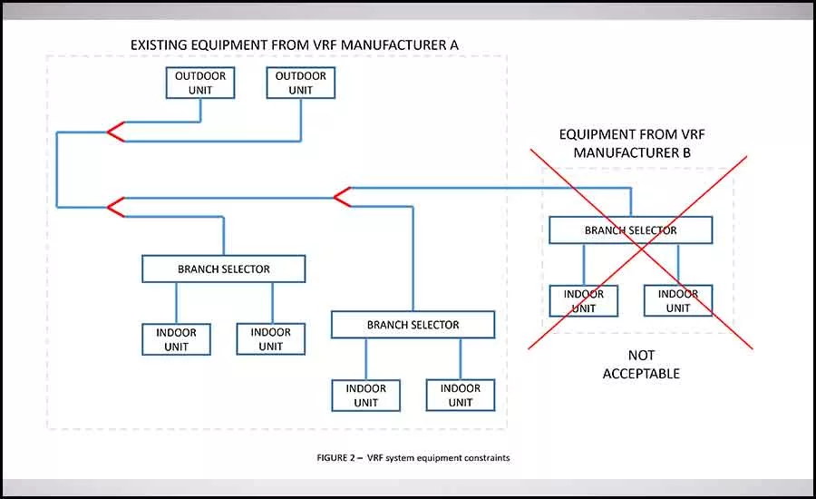
Regardless how different or similar each manufacturer’s installation requirements may be, VRF systems and associated piping configurations are highly proprietary and inherently limiting when it comes to future expansion of existing VRF systems. As shown in Figure 2, it’s important to note that one cannot integrate a VRF system component from one manufacturer into a VRF system provided by another manufacturer. This means that, for the life of the VRF system, a building owner can only use components (i.e., indoor units, pipe fittings, etc.) provided by the same manufacturer.
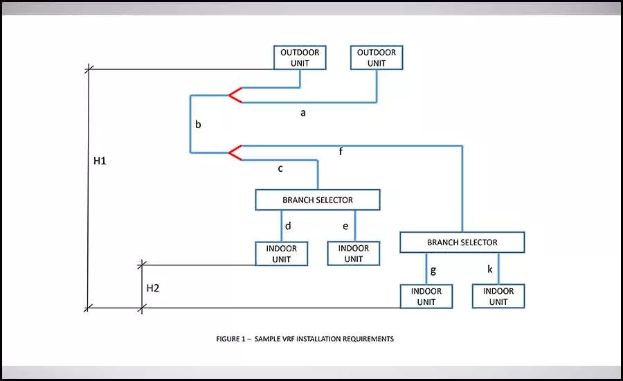
Even if one uses components from the same VRF system manufacturer, expanding a VRF piping system or just connecting into one could prove to be a challenging endeavor. In an ideal case, the existing branch selectors have been oversized in the original design and refrigerant isolation valves have been installed on all piping downstream of the branch selectors; in this scenario, adding and/or relocating indoor units could be a relatively simple effort. However, attempting to insert a new Y fitting in an existing VRF refrigeration piping system will most likely require significant efforts. This is because the VRF manufacturer, through its local representative, will need to analyze the entire piping system and insert all pipe sizes and fittings in the VRF system selection software. Further, all distances between the indoor and outdoor units and between the outdoor units and branch selectors will need to be measured and correctly input into the VRF selection software. Even if the software analysis shows that inserting a new Y fitting in the existing piping is acceptable, there is still considerable risk for the system to not operate as expected; this is because even an error of measurement of a couple of feet could make the system unbalanced.
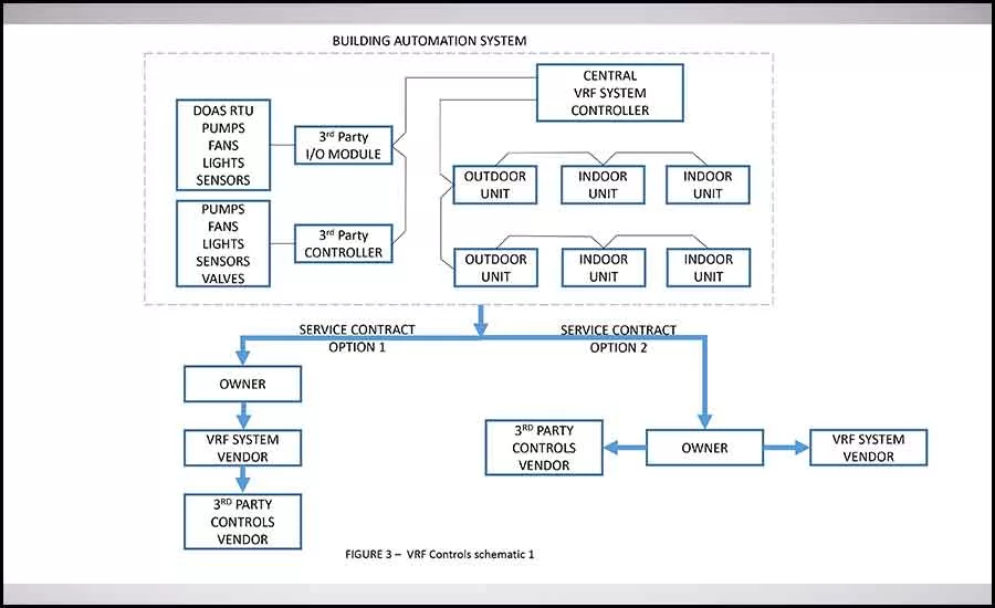
Just like the VRF system piping sizing and layout is specific to a VRF system manufacturer, the same applies to the VRF controls system. Each VRF system manufacturer provides a proprietary controls system to control the associated equipment provided by the same manufacturer. This means that, unlike a more traditional non-VRF system (i.e., chilled water and hot water systems), a building owner does not and cannot choose a separate building automation system (BAS) vendor to control VRF systems. In order to integrate the VRF system controls with other HVAC and lighting equipment, there are a couple of options the engineer could pursue. In the case of relatively small VRF systems, as shown in Figure 3, the VRF manufacturer can provide various third-party input/output (I/O) modules and/or controllers that are capable to control ancillary equipment. It is important to note that any third-party I/O modules and controllers used to integrate into a VRF controls system will need to be certified/supported by the VRF system manufacturer. For simple on/off controls, one could use I/O modules; in general, the sequences of operation used to control and monitor the I/O modules are programmed in the central VRF controller. For more sophisticated controls sequences (i.e., sequences that require analog outputs and inputs) third-party controllers will need to be used. In this scenario, the sequences of operation are programmed in the third-party controller and not in the central VRF controller.
Regardless which VRF controls schematic is being used by the design engineer, careful consideration will need to be paid when selecting and designing third-party I/O modules and controllers. Take, for example, the scenario in which outside air needs to be delivered into an occupied zone without the use of a dedicated outside air system (DOAS). Untreated outside air will need to be ducted into the return side of the indoor unit. It is important to note that any VRF system indoor unit cannot properly handle dehumidification without the risk of overcooling the spaces. As such, a reheat source (i.e., electric reheat coil) will need to be introduced in order to dehumidify the air without overcooling the zone. Since most of the standard VRF indoor unit local controllers/thermostats cannot control non-VRF equipment, a separate third-party controller will need to be added. This controller will need to be designed to control the operation of the reheat coil (by monitoring the RH level in the space) and, in the case of spaces designed with demand control ventilation (DCV), modulate the outside air damper to maintain space CO₂ levels. The design engineer will need to clearly show the design intent on the construction documents such that both vendors (i.e., VRF system vendor and third-party I/O module vendor) have a clear understanding of what needs to be done and who needs to do it. Similarly, the design engineer will need to design and select electric reheat coils based on the expected operation of the VRF indoor unit. In the case of staged duct electric heaters, the operating speed of the fan of the VRF indoor unit will need to be coordinated with the design airflow of the duct electric heater. If the staged duct electric heater is sized for high fan speed and the indoor VRF unit operates at low fan speed, there is a risk of having the discharge air temperature out of the duct electric heater rise above the safety limit, which in turn will trip off the electric heater.
From a service/maintenance contractual perspective, there are typically two options associated with the VRF controls schematic shown in Figure 3. Option No. 1, the owner has only one service contract with the VRF system vendor, which, in turn, has a service contract with the third-party provider. In Option No. 2, the owner has one service contract with the VRF system vendor and a separate service contract with the third-party provider. Typically, owners would choose to pursue option 1 in lieu of option 2 so that there is a single point of responsibility.
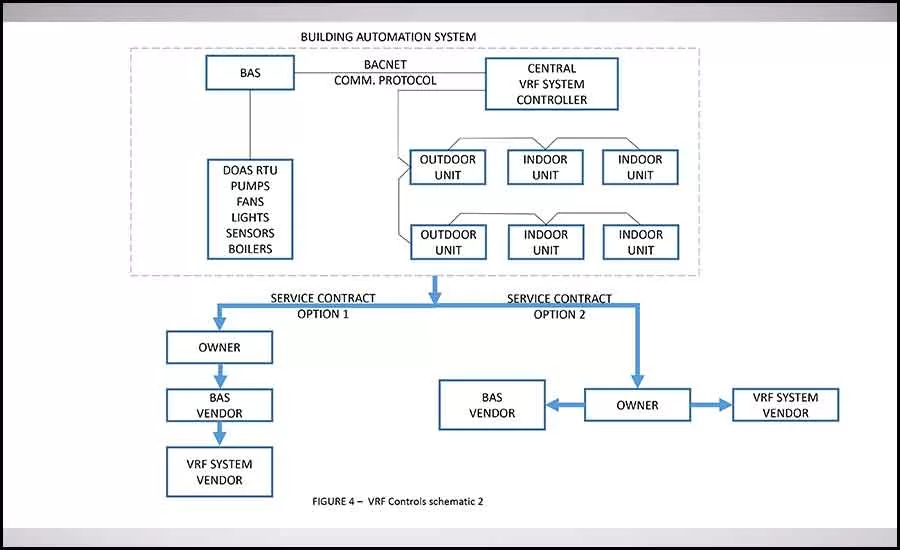
In the case of larger, more complex HVAC and lighting controls systems (as shown in Figure 4), it is common to have a dedicated BAS that controls all non-VRF systems. In this scenario, the central VRF system controller will need to be provided with a BACnet gateway in order for the BAS to recognize it. Depending on the capabilities of the VRF system, some of the functions/commands the BAS can execute via the gateway include: on/off control of indoor units; operation mode (cool, heat, fan, auto, and dry); single set point setting for cooling and heating; fan status; fan speed; and remote controller permit/prohibit of on/off, mode, and set point.
From a service/maintenance contractual perspective, there are typically two options associated with the VRF controls schematic shown in Figure 4. In option No. 1, the owner has only one service contract with the BAS vendor, which, in turn, has a service contract with the VRF system vendor. In option No. 2, the owner has one service contract with the VRF system vendor and a separate service contract with a BAS vendor.
There is no doubt that VRF systems are energy-efficient systems. However, just like with any other building controls system, they are highly proprietary; no matter how efficient they are, the support an owner receives from the local VRF system representative is of significant importance. Poor local support, or lack thereof, may put an undue burden (i.e., unable to fix the system in a timely manner) on the owner of a building. Before proceeding with the design of a VRF system, design engineers need to familiarize themselves with all limitations that come with such highly proprietary systems so they can educate building owners about the benefits and risks associated with the installation and long-term operation of these systems
Looking for a reprint of this article?
From high-res PDFs to custom plaques, order your copy today!


