The Electric Suction Line Regulator
Figure
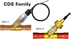
1. Electric suction line regulator. (Figures shown in this feature are courtesy
of Parker Hannifin.)
[Editor’s note: This is the second in a three-part series on one of the newest refrigeration technologies: the electric suction line regulator. The first part appeared in the Jan. 12 issue of The NEWS.]
In the electric suction line regulator (Figure 1), the step motor assembly is connected to the main modulating piston through a gear reduction drive. As the motor rotates in one direction or the other, it will drive the main piston either open or closed. These valves are commonly referred to as electric EPR, EEPR, or electric evaporator pressure regulator valves.
Stand-alone controllers are available for controlling one EEPR at a time, but in the typical supermarket application, every EEPR will be controlled by the energy management system (EMS). The system discharge air temperature signal is relayed to the EMS via the discharge air sensor, which is mounted in the evaporator discharge airstream.
Acting within the parameters of the control algorithm, the EMS sends a signal to the EEPR interface board, which then “steps” the valve more open or closed in response to the discharge air temperature. A system that is maintaining its design discharge air temperature will see the valve operating at a relatively constant valve opening - perhaps 25 percent open with a plus-minus (±) modulation in the range of 3 percent.
It is something of a misnomer for these regulators to be referred to as EEPR valves, because they only respond to discharge air temperature. EEPR valves as applied in supermarkets do not respond to pressure, nor do they maintain a constant evaporator pressure.
It is true that as the valve throttles open, it will reduce the evaporator pressure (along with a corresponding reduction in refrigerant saturation temperature), resulting in a lower discharge air temperature. The fact is, EEPR valves maintain a constant discharge air temperature by varying the evaporator pressure (quite the opposite function of a true EPR valve).
EEPR valves, along with the accompanying EMS and interface boards, are considered current state-of-the-art technology in discharge temperature control. As such, they can provide improved temperature control and increased system efficiency over an application that uses mechanical EPR valves. These are discussed further.
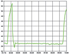
Figure 2. Temperature graph of system using EEPR valve.
TEMP CONTROL, PULLDOWN
Consistent temperature control (Figure 2) is state-of-the art control of the discharge air temperature (within a range of ±0.5°F or less). Given the plus-minus tolerance of the temperature sensor, the control is now getting into a realm where the sensor could not measure anything more accurate. Keeping perishables within this close of a tolerance to the design temperature will yield the longest product life, and reduce fresh meat/produce shrinkage.The pulldown time after defrost termination in this application has been reduced by more than 50 percent with the EEPR (Figure 2). The mechanical EPR starts to throttle closed once the evaporator pressure is down to the valve’s setpoint, regardless of the discharge air temperature.
In contrast, the EEPR valve will continue to operate wide open until the discharge air temperature reaches its setpoint. This allows the evaporator to operate at a lower saturated suction temperature (SST) during pulldown, reducing the discharge air temperature quicker.
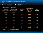
Figure 3. Loss in compressor capacity with suction line pressure drop.
INCREASED EFFICIENCY, REDUCED CONSUMPTION
There are several ways in which the EEPR, along with the proper implementation of the EMS, can increase system efficiency while reducing energy consumption.The simplest way, as previously mentioned, is to prevent the discharge air temperature from falling below the design temperature. Per the manufacturer’s specification, lowering the discharge air temperature below the design temperature would add nothing to product integrity, yet energy would be expended to achieve the temperature reduction.
Any refrigeration capacity dedicated toward lowering the discharge air temperature below the design temperature can be considered a complete waste of energy. With the ability of the CDS valve to control within a range of ±0.5° or less, the possibility of the discharge air temperature operating below the design temperature has virtually been eliminated.
A second way to increase efficiency while reducing energy consumption involves operating the compressors at the lowest possible compression ratio, which is defined as the ratio between the absolute discharge pressure and the absolute suction pressure (abs discharge pressure/abs suction pressure). As the compression ratio increases, compressor volumetric efficiency decreases, lowering the compressor’s pumping capacity.
With the suction pressure as the denominator in the equation, any changes to its value will have the most influence on changing the compression ratio. For this reason, it is imperative to allow the compressors to operate at the highest possible suction pressure; this will yield the highest compressor efficiency and pumping capacity.
For example, unnecessary suction line pressure drop is detrimental on compressor capacity. There can be an approximate 15 percent reduction in compressor capacity between the -25° SST/105° SCT (saturated condensing temperature) condition, and the -20° SST/105° SCT condition on a low-temperature R-404A system - a 3.5-psi pressure drop (Figure 3).
It has been previously discussed that during periods when the load is reduced and/or system conditions have changed, maintaining a constant evaporator pressure will result in a discharge air temperature that can fall below the design temperature. The state-of-the-art EMS can prevent this from occurring by using its floating suction pressure algorithm.
Setup for floating suction control is accomplished in this manner: Assume the wide-island FF cases are the circuit with the lowest operating SST, and a temperature requirement of -23°. The common suction pressure would typically be set to maintain the pressure equivalent for the -25° SST; the design temperature of -23° plus another 2° reduction to account for the temperature change equal to the pressure loss in the suction piping for each circuit. With this being the coldest operating circuit on the rack, every other circuit will easily maintain its respective design temperatures with a common suction pressure equivalent to a -25° SST.
The wide-island FF circuit will be designated the target circuit for the rack, meaning that it becomes the evaporator circuit which the EMS will monitor to determine when it is allowable to float the suction pressure higher than the suction set point of -25° SST. One more thing: The EEPR for this circuit will always be throttled open 100 percent. Because this is the lowest operating temperature circuit on the rack, it would be counterproductive to experience any EEPR throttling on the target circuit. This would indicate that the common suction was lower than necessary to maintain its design temperature, with the compressors running at a correspondingly reduced efficiency.
Once these settings have been entered into the EMS, the algorithm will float the common suction pressure upwards until the discharge air temperature for the target circuit reaches the design set point. This will be the highest allowable common suction pressure to meet the design temperature for all circuits on this rack. Ideally, the lead compressor on this rack will utilize a variable-frequency drive (vfd), allowing virtually unlimited ability to match the suction pressure to the discharge air temperature.
The third aspect of increased system efficiency while reducing energy consumption is based on the ideal that not every circuit on the rack will have critical temperature requirements. Some circuits, particularly wide-island (W/I) boxes, display cases with nonperishable products or less-critical products (canned beverages, water, produce, etc.), and prep a/c areas can tolerate minimal periods when the discharge air temperature is slightly above the design temperature. This thought is the basis for the practice of load shedding - a strategy that selectively allows certain noncritical circuit discharge air temperatures to temporarily float above their design temperature in an effort to reduce the total load on the compressors.
When the target circuit EEPR is 100 percent open, and its discharge air temperature has risen above the design condition, a lower SST will be required to reduce its temperature. This can be accomplished by increasing compressor capacity in one of the following ways:
• If a vfd is employed on the lead compressor, it can initiate an increase in compressor speed.
• Bring a smaller compressor on-line.
• Shut off a smaller compressor and bring a larger compressor on-line.
All three of these actions will reduce the discharge air temperature of the target circuit by reducing the circuit SST. And all three are accomplished by expending the additional energy required to increase the running compressor capacity.
In this scenario, the process of load shedding has the potential to drastically reduce energy consumption. Reducing the mass flow requirement can also lower the SST, thereby reducing the load on the running compressors. We’ll assume that the FF W/I box, bakery W/I box, and the glass door FF meat/fish display have been designated noncritical loads. It is the nature of the product and/or the method of storage that will determine what can be classified noncritical. W/I boxes, when their doors are closed, have a much lower infiltration load than a display case, and will hold their temperatures longer. Frozen meat and/or fish are not as susceptible to spoilage or loss of product integrity as frozen juice or ice cream.
Now, recall that the CDS valve for the W/I FF display cases is operating at 100 percent open. When the circuit discharge air has risen a nominal amount above its design temperature of -23°, say 1° above, the EMS will commence throttling the EEPR valves on the designated noncritical circuits to maintain their new temporary target discharge air temperatures. This reduces the load on the running compressors, causing a reduction in the common suction pressure (and SST), once again allowing the discharge air temperature of the target circuit to reach its design temperature. This is accomplished without bringing on any additional compressor capacity.
Publication Date: 02/02/2009
Looking for a reprint of this article?
From high-res PDFs to custom plaques, order your copy today!


