Step-By-Step Procedures At The Heat Pump Job
At The Jobsite
8:00 a.m. - You arrive at the job. The unit is piped, electrical is connected, low voltage is wired, and the system is charged with nitrogen. The unit is a 2.5-ton, 13-SEER, R-22 model with a matched air handler/evaporator coil. (You will find out what type of metering device is used when you go inside the house.) The system is a new installation; the heat pump was installed in the home yesterday, and a charge of dry nitrogen was left as a holding pressure in the system.The electric furnace has been in operation overnight. Operation of the electric elements was verified yesterday on the initial air handler startup, and it's time to start the cooling. (It's early spring - welcome to Ohio.)
8:10 a.m. - You have notified the customer that you have arrived, explained what you will be checking, and you pet the family dog.

8:17 a.m. - Digital gauges are attached; you left them on overnight tucked into the unit, as it was too late to start the cooling after installing the equipment. The disconnect is in, and 230-V power is applied to the condensing unit (it has been powered overnight). The low-voltage connection is run, but it is not connected to avoid unintentional startup by the customer.
Temperature probe is attached to the suction line, the system is still under pressure, and pressure is verified at 150 psi. Based on the temperature-compensated pressure test done with the analyzer, there are no leaks.
8:19 a.m. - You blow the nitrogen out, attach the vacuum pump, open the ballast on the pump, and start the evacuation. You check the level of oil in the pump. On your check sheet, you jot down the model and serial numbers of the condensing unit and verify the tonnage and type of refrigerant. Then you go inside.

8:30 a.m. - Down in the basement you go. The evaporator fan is running. You shut off the furnace and pull the blower door. The filter looks OK. The motor is a ECM variable-type blower motor. You hand rotate the blower, check the bearings, and make sure the set screw on the hub is tight. You jot down the furnace/air handler model and serial number.
8:35 a.m. - You check the model and serial number of the cased coil and verify that it is matched to the system. Not being familiar with the model number, you have to pull the access door to verify the type of metering device in the system - a thermostatic expansion valve (TXV).
Looking for quick answers on air conditioning, heating and refrigeration topics? Try Ask ACHR NEWS, our new smart AI search tool. Ask ACHR NEWS
8:42 a.m. - With the door off (to make sure you don't drill through the coil or the drain pan), you drill a 1/4-inch hole below the air handler just below the cased coil cabinet and another in the supply plenum to measure the total external static pressure drop through the air handler. The doors, coil, and blower then get reinstalled.

You record the required and actual airflow on the sheet. The manometer is removed and the holes are plugged with Thumb-Gum® and the airflow is set. The air handler is then shut off.
9:00 a.m. - (Yes, a proper startup will take more than an hour, but you won't be back for the no-charge warranty call.) Back out at the condenser, the unit is down to 1,000 microns. You close the gas ballast and let the pump continue to run. You pull the disconnect and remove the access panel. Gently tugging on the electrical connections, all appears OK. You verify the wire size and fuses and connect the low voltage. The disconnect is left removed.
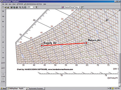
9:10 a.m. - You head back inside and don the booties again. Back down in the basement, you turn back on the power to the furnace and measure the conditions of the return air in the cold air drop. The entering (return air) wet bulb and dry bulb are recorded. You then move the humidity stick to the supply air duct a few feet from the coil. You leave the furnace running.

9:32 a.m. - You isolate the micron gauge, remove the service valve caps, and cut in the charge. Knowing that this is a TXV-type metering device, you move the temperature probe to the liquid line to charge by subcooling. You set the digital manifold up to log every 20 seconds, push in the disconnect, and the system starts. The low side starts to come down, the high side goes up, and the system starts to cool.
While the system is settling out, you take the electrical measurements, volts and amps, and start taking some of the tools back to the truck.
9:40 a.m. - The system has settled out, the subcooling is running at 2 degrees, the manufacturer's chart calls for 7 degrees - the system is slightly undercharged. You head back to the truck for an R-22 tank and a scale.
9:45 a.m. - You slowly add refrigerant to the low side of the system allowing time for the charge to settle as you watch the subcooling on the analyzer. Eventually you add 9 ounces of R-22 to the system. Watching the digital manifold set, the subcooling soon drops to 7.5 degrees. It is within the manufacturer's guidelines, so you leave it. You record the refrigerant in the refrigerant log in your billing book.

9:55 a.m. - The cooling is done!
9:57 a.m. - It's a heat pump, so we need to verify the operation in heating. The thermostat is switched from cool to heat and the unit is given time to settle. The temperature rise across the indoor coil is verified. And the operating pressures are compared to the heating charging curves on the compressor access panel. Almost all manufacturers recommend the final system operation is verified in the cooling mode, so the charge should not be adjusted.
10:15 a.m. - You stop the logging process, remove the gauge set, make sure the caps are installed on the Schrader ports, disconnect the power, and reinstall the access panel. Then you reinstall the disconnect. You make sure that all the paperwork is complete, and carry the rest of your tools back to the truck.
10:30 a.m. - You have explained the system's operation to the homeowner, moved the thermostat back to its original settings, and get your paperwork signed. It's time to call in for the next customer.
Back At The Office
The information from the manifold set is downloaded into the computer. The service manager verifies correct operation by viewing a graph of the system operation. The cfm and entering and leaving air conditions are entered into the psychrometric program; a report detailing the latent, sensible, and total Btuh capacity of the unit is generated.The system is operating as designed. A copy of the report is filed, sent to the homeowner, and the true operating conditions that were logged are sent in for third-party verification.
Did it take any longer? With the time you saved using digital instrumentation, most likely not. The airflow and charge were checked in a matter of minutes. The charge verification was done with tamperproof equipment data, the airflow can be verified by the equipment design, and the data recorded by the digital manifold set.

What is your time really worth? If you do it right the first time, you will not be back out again until next year for spring service.
Do it right. Do it once. Work smarter, not harder.
Jim Bergmann teaches at Cuyahoga Valley Career Center, Brecksville, Ohio.
Publication date: 05/23/2005
Looking for a reprint of this article?
From high-res PDFs to custom plaques, order your copy today!


