Troubleshooting the Refrigeration Cycle for Mechanical Problems

Similar to the human heart, the refrigeration compressor needs to be properly maintained and requires periodic inspection and testing. Unfortunately, the compressor is often ignored until it malfunctions or stops running altogether, at which time it gets replaced and the system is back up and running - temporarily. Oftentimes the culprit is not the compressor, but a system failure or design problem with accessory equipment which killed the compressor prematurely.
This article describes how to troubleshoot a compressor and the associated problems that can cause a system to fail prematurely. We will discuss the proper methods of diagnosing and repairing system problems, rather than just their symptoms.
MEASURING THE COMPRESSOR SUCTION AND DISCHARGE PRESSURE
Both the suction and discharge pressures at the compressor are normally measured with a standard set of refrigeration gauges. However, this article will explain how to measure both pressures on the suction and high side of the system with your digital multimeter (DMM) and a pressure/vacuum module, with or without your standard gauges. If the gauges are left on the system and used in conjunction with this test, the module will verify the accuracy of the standard manifold gauges.To measure the pressures on your DMM in conjunction with your standard manifold gauges, take the following steps:
To read the suction pressure on your DMM, open the blue handle on the manifold gauges. This puts the system suction pressure into the pressure/vacuum module. Read the pressure on the digital readout and compare it to the gauge pressures. Don't be alarmed if the pressures don't match exactly. Modules like the Fluke PV350 are typically much more accurate than a standard set of refrigeration gauges. To read the discharge pressure on your DMM, close the blue valve on your gauges and open the red handle on the manifold gauges. This puts the system discharge pressure into the module.
To remove the module, simply reverse the process you followed when installing the unit.
Caution: Be sure to close the high side port of your gauges first, and remember to remove the refrigerant from the high side gauge by allowing the compressor to run and pull excess refrigerant into the low side of the system.
To measure the pressures on your DMM and pressure/vacuum module without installing your manifold gauges, take the following steps:
You can read one pressure at a time using a single pressure vacuum module, so you will need to record the suction or discharge pressure one at a time. Or if you are using a DMM meter such as a Fluke 179 with a min/max feature, you can record the suction pressure as the min value and then record the discharge pressure as the max value.
To remove the pressure/vacuum module, simply reverse the process you followed when installing the unit.
Caution: Be careful when removing the high side port of your gauges as it can be under very high pressure. To minimize refrigerant loss, learn to practice safe refrigerant handling habits when removing the module from the high side of the system. This includes shutting off the compressor prior to gauge removal and allowing the pressure to equalize. When removing the gauge from the low side of the system it is not necessary to first shut down the compressor.
TROUBLESHOOTING THE COMPRESSOR DISCHARGE LINE TEMPERATURES
Pressure and temperature are fundamental tests that you can perform to determine what is happening inside the compressor. To learn the proper methods to check the refrigerant superheat and subcooling at the compressor, refer to the Fluke application note titled, "Troubleshooting HVAC/R systems using refrigerant superheat and subcooling."To measure the temperature of the compressor, take the following steps:
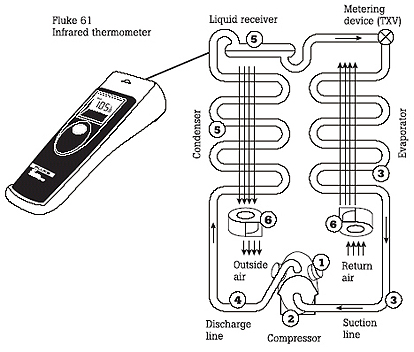
A temperature survey is a critical part of the service technician's job. A quick check of a system's components not only helps to diagnose troubles but also allows you to anticipate failures by regular monitoring of critical temperatures. Use an infrared thermometer to do a quick survey of:
With an infrared thermometer, you can quickly survey a refrigeration system by scanning the temperatures of various components (see Figure 1). While touching each of the components often does this, a noncontact infrared tool is faster. By keeping careful records, it is possible to detect trends that indicate impending failure. This allows you to keep the system in top condition and avoid costly failures.
Note: IR instruments read best when measuring an object with a dull (not shiny) surface. If the surface is shiny, dull it with either black markers, non-gloss paint, masking tape, electrical tape, etc. For more information on taking temperature measurements with an IR thermometer, refer to the Fluke application note titled "Non-contact temperature measurements using IR thermometers."
RECORDING A TEMPERATURE OVERNIGHT
To check refrigeration system performance, it is often useful to record temperatures in the refrigerated space. This allows you to detect problems that may go unnoticed with a single system check.For instance, in a refrigerated space it is important to ensure that temperature variations are minimized. Temperature variations may result from changes in load or ambient conditions that occur over periods of time, so constant monitoring is called for. By recording minimum and maximum temperatures in key locations over a period of time you can be sure that air circulation and refrigeration capacity meets the application requirements.
Digital recording thermometers allow you to record minimum and maximum temperatures over extended periods of time. Temperature values can be viewed at any time by pressing the view button (recording still continues). If the HOLD button is pushed, the recorded MIN/MAX values are saved and recording stops. The data is saved until the user selects a different input or turns off the instrument. Some DMMs can also measure MIN/MAX of a single temperature, plus they offer the benefit of a 100-hour relative time stamp to record when the MIN/MAX occurred.
When selecting a digital recording thermometer, look for a model that can record hundreds of temperature samples so you get precise measurement. Additional features that are helpful include a time stamp feature, operator interval settings, and dual channels to record two temperatures at the same time. With this type of device you can record temperature difference across a coil for extended periods of time. This feature is especially handy for troubleshooting erratic problem areas of the HVAC equipment where time limitations do not allow the technician to wait until the problem occurs.

COMPRESSOR VALVE PERFORMANCE TEST
To test small hermetic and semi-hermetic compressors used for medium and low temperature applications, the following method can be used to test for internal valve leakage. (See Figure 2.)The compressor should have pulled down to at least 16 inches (410 mm) of Hg. If the vacuum reading starts weakening toward 10 inches (254 mm) of Hg vacuum, the discharge valves of the compressor may be leaking and will probably need to be replaced. If the compressor doesn't pull a vacuum below 16 inches Hg, the suction valves are weakening and may need to be replaced. If the compressor is welded or hermetically sealed and these conditions exist, a new compressor is the only possible remedy.
Caution: Whenever replacing a compressor with faulty valves, be sure to diagnose the complete refrigeration system before and after a new compressor is installed to avoid repeated compressor failures.
TROUBLESHOOTING COMPRESSOR ELECTRICAL MOTOR FAULTS
A clamp meter is a great tool for troubleshooting electrical motor faults, especially meters designed to accurately measure both AC voltage and AC current. These meters allow current to be measured without breaking into the electrical circuit. A compressor failure is often caused by an electrical fault. To check the compressor for electrical problems, remove the electrical terminal cover and check the following external connections.1. Check line voltage at the load center with the compressor off. Low line voltage causes the motor to draw more current than normal and may result in overheating and premature failure. Line voltage that is too high will cause excessive inrush current at motor start, again leading to premature failure.
2. Check line voltage at the motor terminals with the compressor running. The voltage should be within 10 percent of the motor rating.
3. Check running current. The readings should not exceed manufacturer's full load rated amps during heavy load periods. Low amps are normal during low load conditions. Excessive high current may be due to shorted or grounded windings, a bad capacitor, a faulty start relay, or an indication of excessive bearing fatigue.
Caution: When performing electrical measurements on compressors with internal thermal motor protection devices that have been running extremely hot, be sure to give the compressor time to cool down prior to the electrical test. This will allow the device to reset to its normal position.
TROUBLESHOOTING COMPRESSOR ELECTRICAL MOTOR FAILURES CAUSED BY REFRIGERATION SYSTEM PROBLEMS
Occasionally defective compressors with electrical winding failures are diagnosed by a service technician as caused by an electrical system problem. However, mechanical system failure or inferior installation and service practices often cause compressor electrical problems. These problems include:1. Poor piping practices resulting in oil not adequately returning to the compressor during the run cycle.
2. High discharge temperatures creating acids in the oil.
3. Insufficient airflows across the evaporator and condenser coils.
4. Extremely low suction pressures.
5. Liquid refrigerant flooding back into the compressor.
Diagnosing these refrigeration system problems and avoiding compressor failure can be done effectively using DMMs, clamp meters, digital thermometers, pipe clamps, infrared thermometer, and pressure/vacuum modules.
Here are some simple procedures to diagnose these refrigeration problems:
1. Compressor bearings can fail or lock up due to poor piping practices, which causes oil clogging in the system and results in insufficient oil return to the compressor. If the bearings don't lock-up and continue to wear during these conditions, the rotor will lower into the stator housing, shorting out the windings. To diagnose this problem, measure the compressor amps. They should not exceed the manufacturer's full load ratings. Worn bearings will cause higher than normal amps. Inspect the oil level via the compressor sightglass. If there is no sightglass, use your infrared thermometer to measure the sump of the compressor housing. The oil level can be detected with the temperature probe. The sump temperature will be different on the compressor housing at the oil level.
Caution: Whenever an oil problem exists due to poor piping practices, the correct remedy is to fix the piping, not to continue to add more oil to the system.
2. High discharge temperatures are caused by high head pressures or high superheat. The compressor discharge line can be measured quickly using the infrared thermometer on a dull section of pipe. Measure the discharge pressure using a pressure/vacuum module. Convert the refrigerant pressure to temperature and compare it to the ambient air temperature. If there is a temperature difference greater than 20-30°F (11-17°C), there is either noncondensible gases in the system or restricted airflow across the condenser.
Note: Temperature differences will vary due to original manufacturer's design and efficiencies.
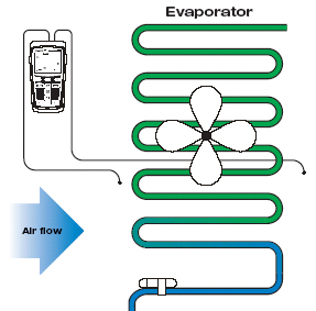
3. Check for insufficient airflows across the evaporator using a digital thermometer. (See Figure 3.) Place a bead thermocouple on the discharge side of the coil and on the return side of the coil. Record the temperature difference on the air conditioning unit. Expect about 18-22°F (10-12°C) temperature difference. On refrigeration units, expect about 10-15°F (5-8.5°C) temperature difference.
Note: Temperature differences may vary depending upon initial design and humidity requirements.
4. Extremely low suction pressures can be checked using the pressure/vacuum module and your DMM. Install it at the compressor and record your suction pressure. Convert the refrigerant pressure to temperature using a pressure-temperature (PT) chart. Measure the return air temperature before the evaporator. Compare the refrigerant temperature to the desired evaporator return air temperature. On air conditioning units, expect about 35-40°F (19-22°C) temperature difference and, on refrigeration units, expect about 10-20°F (5-11°C) temperature difference.
5. Check for liquid refrigerant flooding back to the compressor by determining the superheat using your pressure/vacuum module and pipe clamp, along with your DMM. Check suction pressure and convert the refrigerant pressure to temperature, using your PT chart. Measure the suction line pipe temperature. Compare the difference of the two temperatures. If there is no temperature difference, then you are bringing back liquid to the compressor. If there is a temperature difference between 10-20°F (5-11°C), then you have normal superheat and you are not slugging the compressor with unwanted liquid.
SUMMARY
Troubleshooting and servicing refrigeration, air conditioning, and heat pump systems is a challenge for any technician, entry level or experienced. Regardless of the size or location of the system, it is imperative that the service technician understands the principles and the tools needed to perform proper troubleshooting efficiently.Reprinted with permission from the Fluke Corp. Application Note "Troubleshooting the HVAC/R refrigeration cycle for mechanical problems." For more information, visit www.fluke.com.
Publication date: 02/06/2006
Looking for quick answers on air conditioning, heating and refrigeration topics? Try Ask ACHR NEWS, our new smart AI search tool. Ask ACHR NEWS
Looking for a reprint of this article?
From high-res PDFs to custom plaques, order your copy today!


