Correct Installation of the Relief Air Plenum Pressure Sensor
Ensuring accurate measurement and control in air handling unit operations

RELIEF: Proper placement of the relief air plenum pressure sensor ensures accurate control and stable operation of air handling units.
A common component of a control strategy for a recirculating AHU with a return fan is the incorporation of a relief air plenum pressure sensor. This sensor is sometimes used for monitoring only, but is also often utilized for control of the relief air damper or return fan (see Figure 1). This article is written in the context of the relief air damper being controlled to maintain that sensor reading at a prescribed setpoint; however, all of the points made regarding the installation of the sensor also apply when the return fan is modulated to maintain that sensor reading at setpoint.
The Intent
The rationale for having the relief air damper control for that pressure is to ensure that the relief damper remains closed when a negative pressure is being experienced in the relief air plenum. If that damper were to be open in such scenarios (which can often be the case in control strategies that do not incorporate this component), then air will be sucked in backwards through the relief air duct. Essentially, the relief air duct becomes a second outdoor air duct, but the quality of this “outdoor air” is questionable in many instances.
Codes do not have as many limitations for the placement of the relief air louver compared to an outdoor air louver. Additionally, the relief air from multiple AHUs may often share a common relief air louver. Therefore, sucking air backwards through the relief air duct may pose significant air quality concerns.
The Common Misapplication of this Sensor
Where this strategy becomes ineffective is when the low-pressure reference port for the differential air pressure transducer is not measuring the correct reference pressure. Flow direction through that relief air damper will be dictated by the relationship (positive or negative) of the differential pressure across that damper. Therefore, best practice is to use the downstream side of the relief air damper as the low-pressure reference for the transducer.
Scenario 1: Ducted Relief with the AHU Located in a Mechanical Room
It is common for the low-pressure port to be specified and/or installed referencing the mechanical room in which the AHU is located. If the relief air is ducted to the outdoors, this is not going to work correctly. The mechanical room pressure would not be representative of the pressure downstream of the relief damper.
If a mechanical room’s absolute pressure trends higher than the absolute pressure downstream of the relief air damper, the relief air damper will stay closed for longer than it should upon a rising economizer signal (i.e., closing of the return air damper), which will make the return fan work harder than it needs to.
If a mechanical room’s absolute pressure trends lower than the absolute pressure downstream of the relief air damper, then the sensor’s differential pressure reading would be higher than it should be. The relief damper may open prematurely, air would enter the relief plenum by traveling backwards through the relief air duct, the relief plenum differential pressure reading would actually increase when that happens, which would result in the relief damper opening further, and the whole process would spiral out of control. The control loop becomes unstable in such situations.
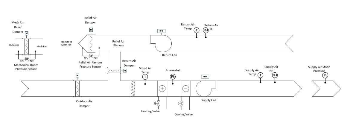
FIGURE 1: AHU with ducted relief air. Relief plenum pressure low port needs to reference air downstream of relief air damper. (Courtresy of Questions & Solutions Engineering)
Scenario 2: AHU Relieves into the Mechanical Room it is Located in
Referencing the mechanical room air for the low-pressure port is acceptable if the unit relieves into the mechanical room, because the mechanical room pressure is representative of the relief air damper’s downstream pressure in this scenario. In many cases, referencing the mechanical room may be the only option with this type of AHU configuration (see Photo 1). This configuration usually incorporates a separate system for control of mechanical room pressure. One such example would be a separate mechanical room relief air damper, which controls to a differential pressure across it (see Figure 2). When the AHU starts relieving into the mechanical room, the mechanical room pressure builds in reference to the outdoor air, and that additional mechanical room relief damper eventually opens.
For the configuration shown in Figure 2, it is imperative NOT to reference the AHU’s relief plenum pressure sensor’s low port to the outdoor air. I have seen that attempted, with the AHU’s relief plenum pressure setpoint set higher than the mechanical room pressure setpoint. In theory, that could work. The risk here is that the setpoints could be incorrectly adjusted or become uncoordinated, and the approach will cease to work.
Since the AHU’s relief air plenum pressure transmitter was physically located at the control cabinet in the mechanical room, we merely unhooked the low reference tube leading to the outdoors and plugged it.
Scenario 3: RTU Located Outside
Referencing the outdoor air as the low-pressure port is acceptable in this scenario, since the outdoor air pressure is representative of the downstream pressure of the relief air damper. RTUs would rarely have the air ducted downstream of the relief air damper.
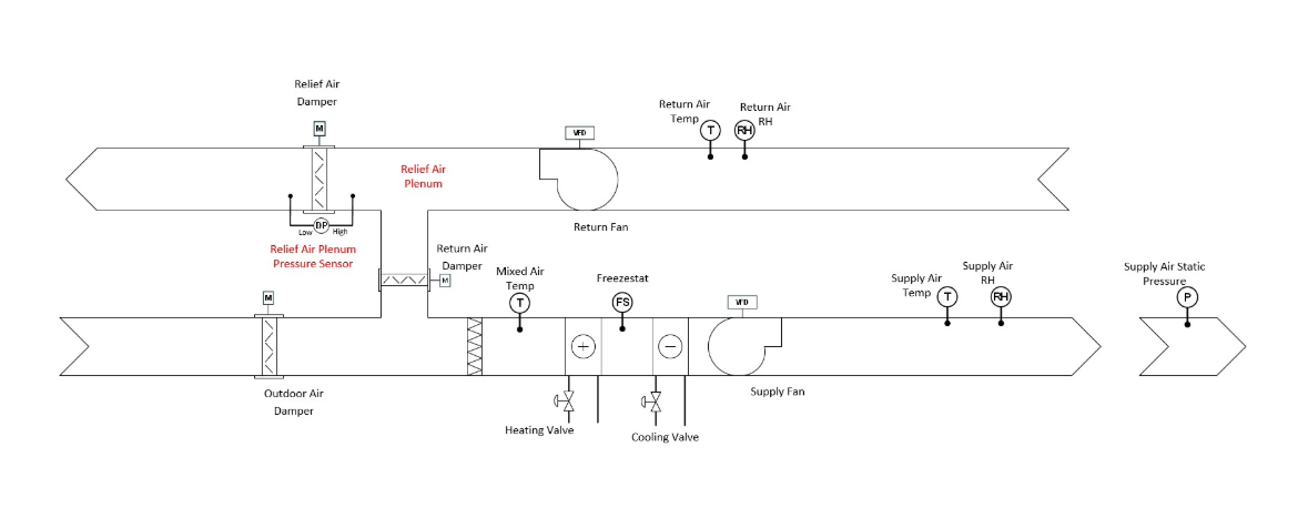
FIGURE 2: AHU relieving directing into a mechanical room. Relief plenum pressure low port can reference mechanical room in this instance, since that pressure is representative of the downstream pressure of the AHU’s relief air damper. Mechanical room pressure control performed by a separate system. (Courtesy of Questions & Solutions Engineering)
Additional Considerations
When implementing this approach, the control strategy for the relief air damper needs to be coordinated with the return air damper so that a faulty sensor reading does not result in both dampers closing and deadheading the return fan.
Along those lines, an in-unit static pressure safety switch that measures the relief plenum pressure relative to the mechanical room (or ambient, if an RTU) is advised to disable the entire unit should either the lower of the pressure rating of the unit or the deadheaded differential pressure of the return fan be exceeded.
Lastly, the relief plenum pressure sensor should be specified as a bidirectional sensor, capable of reading both positive and negative values. This will provide more useful information to the building operator, because there may be situations when the relief damper is fully closed. Having a negative reading on the relief plenum sensor displayed on the BAS would provide the building operator with an explanation as to why the damper is closed.
Conclusion
Correctly referencing the relief air plenum pressure low port sounds trivial, but is often incorrectly specified and/or installed. This has led to many time-consuming troubleshooting exercises. Taking the time to truly think it through can save many headaches. Hopefully, these explanations will help commissioning providers better articulate the issue to design engineers and temperature control contractors.
Captions:
Figure 1: AHU with ducted relief air. Relief plenum pressure low port needs to reference air downstream of relief air damper.
Photo 1: AHU relieving directly into a mechanical room.
Figure 2: AHU relieving directly into a mechanical room. Relief plenum pressure low port can reference the mechanical room in this instance, since that pressure is representative of the downstream pressure of the AHU’s relief air damper. Mechanical room pressure control is performed by a separate system.
Looking for a reprint of this article?
From high-res PDFs to custom plaques, order your copy today!