Geothermal Heat Pump Well Innovations Toward Building Electrification
The largest obstacle to geothermal heat pump adoption has always been the wells and their associated costs.
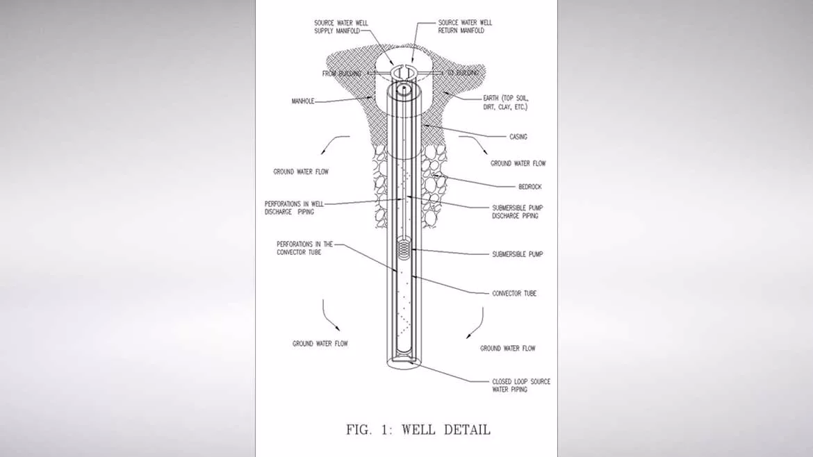
FIGURE 1: Details of a convection enhanced geothermal heat pump (CEGH) well. Images courtesy of Aztech Engineers Inc.
Building electrification is becoming a major approach in fighting climate change and reducing emissions. As electrical generation becomes cleaner with wind, solar, and hydro, building electrification makes sense. Concurrently, the air-source heat pump market has been on a steady rise with the adoption of inverter-based technology. Though the newer air-to-air heat pumps can keep heating with the refrigeration cycle down to lower outdoor air temperatures there are inefficiencies at these lower temperatures trying to absorb heat from 0°F air.
Geothermal units, or ground-source heat pumps (GSHP), solve the low-temperature issue as the ground is at a constant 50°-60° temperature, providing much better efficiencies during heating and cooling. The largest obstacle to geothermal heat pump adoption has always been the wells and their associated costs. Closed GSHP wells do not require environmental permitting are not that dependent on ground water flow but do not have efficient heat transfer with the ground and, as such, require a lot of well per ton. Many vertical wells would be required for even a modest commercial building. Open-loop GHSP wells provide better heat transfer efficiency but are dependent on considerable local ground water flow, reinjection is very difficult, and they usually require extensive environmental permitting.
What if there was a GSHP well that took the best of both systems; one that is completely closed loop but with much greater capacity per linear foot; one that could make GSHP systems practical for larger commercial buildings. The convection enhanced geothermal heat pump (CEGH) well may be that well. The problem with closed-loop wells is that they rely only on conduction through nonconductive material for heat transfer to the ground. The CEGH is a closed-loop well/system that increases heat transfer with the ground by inducing ground water flow around the well piping, thus adding convection to the heat transfer process. A polyvinyl chloride (PVC) tube is installed in the center of the well (convector tube) with strategically drilled perforations. The well piping is routed down the well between this tube and the well’s outer walls. A typical submersible pump is placed in the approximate center of the tube. The submersible pump moves the ground water from the bottom half of the well to the top and distributes it radially around the well piping through perforations in the PVC center tube and cap and baffle placement.
The CEGH is patented, and a prototype has been built and comparison-tested against a conventional closed-loop well. The CEGH showed significant heat transfer and absorption gains over the over the conventional well in the test. To prove the concept, a test was derived that provided quantitative data and information of the performance of the CEGH in comparison to a conventional well. As the CEGH is a totally new concept, no test has yet been developed. So, a tester, or test assembly, as it will be referred to, was designed and constructed. The custom test assembly enabled flexible use and custom data acquisition. One borehole was drilled. A conventional closed-piping loop was inserted into it, and a thermal absorption test was run on that loop. Then, the conventional closed-loop piping was removed so that the CEGH assembly could be installed in the same borehole, and the same exact test and measurements were performed on the CEGH.

Heated water was circulating at a constant rate through each well assembly, and the water temperature entering and leaving each well and water flow in gallons per minute (gpm) were measured and recorded. British thermal units per hour (Btuh) and total British thermal units (Btu) absorbed by each test well (conventional and CEGH) were derived from water temperature and flow measurements.
Test Assembly Construction
An electric boiler, pumps and the required hydronic specialties (pressurized system) were all constructed in an aluminum, weatherproof enclosure. A (Thermolec Model B-15U-FFB, 51,180 Btuh capacity, 15 kW, 208V/3Ø) electric boiler with silicon-controlled rectifier (SCR) control was used. The SCR enables modulating boiler output control (as opposed to on/off) to maintain discharge water temperature closely without a dead band. A three-speed Grundfos pump was used to circulate the water through the well and test assembly in the source water piping. A Dwyer Instruments Series MFS2 Magnetic Inductive Flow Sensor was also installed in the test assembly and ACT A/TTK-1-2.5-inch-GD water temperature sensors were installed at the inlet and outlet of the boiler and test assembly. The flow sensor measured water flow in gpm, and the temperature sensors measured temperature in degrees Fahrenheit. All five measuring devices are tied into a Dataq Instruments DI-808 Web Based Data Logger. In the end, the test assembly produced a consistent flow of water with constant heat to the well. These flow and temperatures were measured and recorded every couple of minutes for several days for each test.
Prototype Construction
Lengths of straight 3-inch” PVC pipe (convector tube) with six ¾-inch HDPE pipes along the outside of the PVC pipe with well gaskets at different locations were fed 400 feet into a 6 ½-inch inside diameter borehole. The six ¾-inch HDPE pipes start as approximately 3-foot-diameter coils. Six coil holders with rollers and pipe straighteners made of rollers were fashioned to hold the HDPE coils and assist in lowering the pipe into the borehole. Rolling or unwinding the coil feeds the pipe out through the pipe straighteners and then down into the well.

Small holes of varying sizes were drilled into the convector tube along its length. A well gasket is located at approximate the middle of the well to hydraulically separate the bottom (suction) half of the well from the top (discharge) half of the well.
The submersible pump with its electrical power connection and tube gasket were lowered down into the convector tube to its approximate middle. A “tube gasket” was constructed to fit the space between the pump discharge piping and the convector tube and hydraulically separates the top half (discharge) of the convector tube from the bottom (suction) half. The tube gasket is located at the same approximate level as the well gasket. Holes were drilled in some of the discharge pipe lengths for the pumped water to discharge into the interior of the convector tube, through the tube’s perforations, and into the well and Earth.
Three of the six ends of the ¾-inch HDPE pipe coming out of the well were connected to three ¾-inch and one 1 ¼-inch pipe manifold. The other three ends were connected to another similar manifold to make an inlet to the well from the test assembly and an outlet back to the test assembly. One of the 1 ¼-inch pipes was connected to the inlet of the test assembly, and the other to the discharge of the test assembly, just as with the conventional base case test. The test assembly and well were filled with water, the test assembly was started, and the test was run as it was for the base case conventional well.
Results and Analysis
The water flow (gpm) and water temperatures entering and leaving the test assembly and boiler were continually measured throughout each test run. These measurements were recorded every two minutes by the data logger and made available in CSV files. Heat absorbed by the well in MBH is determined from the flow and test assembly water inlet temperature (or well return water temperature [RW]) and the test assembly outlet temperature. The test assembly system was typically putting out about 40 MBH into the well system.
Table 1 summarizes the test results by indicating the cumulative heat absorbed by the well with the different assemblies in them (conventional and CEGH) calculated from the measurements at the first two-minute recording after each test’s return water temperature reaches the milestone temperatures of 70°, 75°, 80°, 85°, and 90°.
|
RETURN AIR WATER TEMP (°F) |
CEGH 5-2018 |
BASE CASE |
||
|
TIME ELAPSED (HOURS) |
CUM HEAT ABSORBED (KBTU) |
TIME ELAPSED (HOURS) |
CUM HEAT ABSORBED (KBTU) |
|
|
70° |
4.07 |
193.41 |
1.37 |
60.34 |
|
75° |
8.37 |
328.8 |
3.20 |
141.79 |
|
80° |
16.03 |
633.21 |
6.50 |
293.06 |
|
85° |
31.60 |
1233.19 |
13.17 |
594.59 |
|
90° |
69.36 |
2646.53 |
23.97 |
1097.10 |
The test performed simulated a heat pump system in cooling mode, where the well is absorbing the heat of rejection from the heat pump’s refrigeration system. The return water temperature is the temperature of the water coming out of the well that would be going back in to heat pump system to “cool” the system’s condensers. Water temperature entering a heat pump (return water temperature from the well) above 90°F is not that useful. The return water temperature relates to the well temperature. As the well temperature rises, heat exchange with the well (ground) is reduced as the delta T between the water entering the well and the surrounding ground is reduced. As the above summary shows, it took the CEGH 69 hours and 2,646.53 MBtu of total heat energy before the RW temp rose to 90° while it only took only 24 hours and 1,097.10 MBtu for the RW temp of the base case (conventional well) to get to 90°. Thus, the CEGH absorbed 2.4 times more heat than a comparable conventional closed-loop well before reaching the end of the useful well return water temperature, meaning that the CEGH could have approximately 2.4 times the capacity of a comparable conventional closed loop well.
Conclusions
The prototype test proved the main concept of the CEGH. By inducing ground water flow around the piping of a closed-loop geothermal heat pump well, the capacity of the well can be increased. It also showed that the general design and construction of the CEGH works to induce ground water flow around the well piping. A functional system that rendered very positive results was accomplished in the first attempt, which encourages the notation that this is a feasible concept.
There is very strong reason to believe this CEGH well in this location and installation was not optimal and that better results can be expected for future installations in different locations. Bedrock was not hit until 120 feet down, and water was not reached until about 250 feet down. Steel casing covered the first 120 feet of this test well, and the rock from 120 feet to about 250 feet was tight with very few cracks that water could pass through. As the conventional closed-loop geothermal well depends only on conduction, this condition did not affect its performance. However, the CEGH was likely very affected by this condition with only about 150 feet out of the 400 foot well usable for convection (ground water flow).
Looking for a reprint of this article?
From high-res PDFs to custom plaques, order your copy today!


