Stacking a Centrifugal Chiller Plant at VCU's Siegel Center
How and why WSP opted to replace an existing ice storage plant with a hidden modular centrifugal chiller plant.
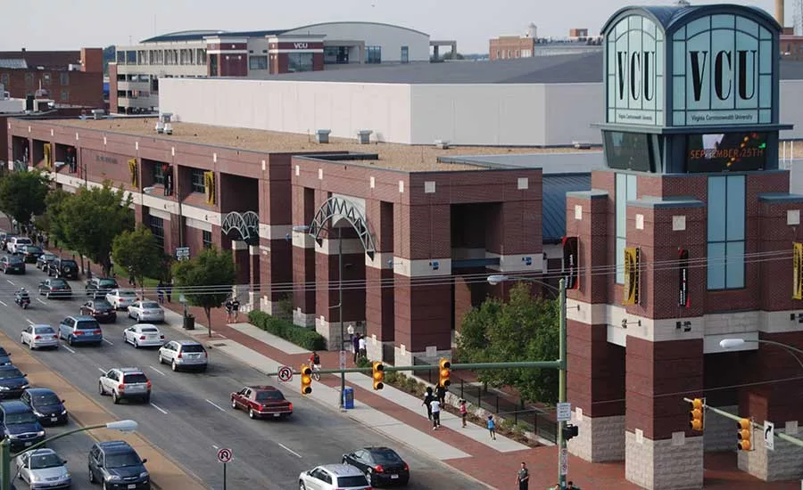
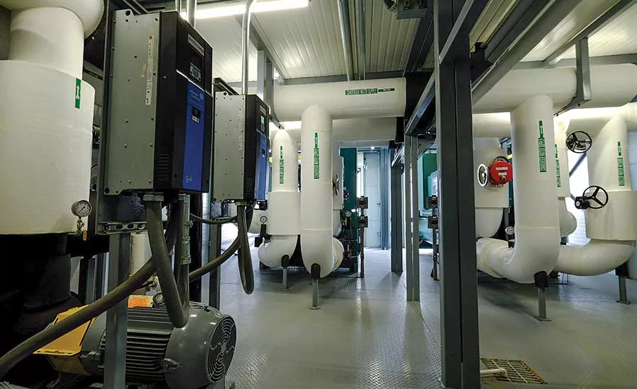
FIGURE 1. Two 500-ton centrifugal chillers sit inside the new modular plant with condenser water pumps and VFDs seen on the left. The two halves of the plant are joined together along the seam in the floor running between the two chillers.
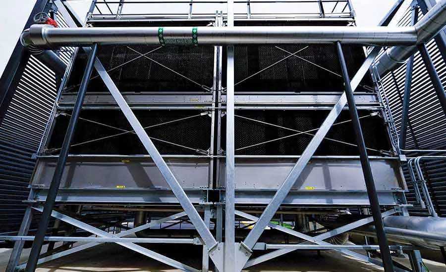
FIGURE 2. Providing heat rejection to the chiller plant are two 500-ton cooling tower cells, which are concealed from public view by a louvered screenwall.
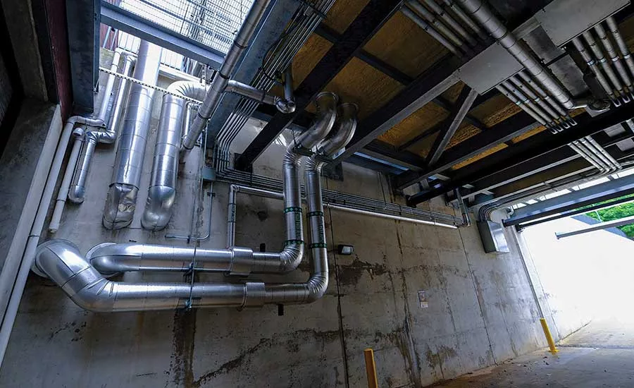
FIGURE 3. Cover is provided to the facility’s loading dock by the new modular chiller plant. Chilled water connections are seen penetrating the bottom of the plant and are routed into the building. Electrical feeds to the plant are seen routed to a pull box on the loading dock wall from which the feeds travel underground to the building’s main electrical room.
The Stuart C. Siegel Center at Virginia Commonwealth University (VCU), located in Richmond, Virginia, is mostly known for its sold-out men’s basketball games, but it also hosts several other events and activities. From an air conditioning perspective, the basketball games do not account for the highest peak cooling load of the year for the 7,637-seat arena.
Every June, the Siegel Center fills with students, family members, and staff for roughly 35 high school graduations that are held back to back over an 11-day period, putting a constant, high cooling load on the building during the peak summer month. The facility was originally constructed with an ice storage system, which was sized to provide cooling to one basketball game each day. While an ice plant offers an opportunity for end users to utilize lower demand charges by creating ice during off-peak hours, it falls short when trying to maintain a constant high-demand load. At graduation time, the ice system could provide cooling to the first graduation ceremony of the day but was depleted by the second and third graduations, causing the facility to experience a rise in indoor temperature and humidity.
Expensive rental chillers were being used to supplement the chilled water system as a remedy to this problem, but a longer-term solution was needed. WSP was approached to develop an efficient solution to the building’s cooling demands. The firm determined the existing systems serving the Siegel Center were not functioning properly. The original chilled water system in the Siegel Center was installed in 2000. It was an ice slurry system consisting of two 250-ton condensing units capable of 1,000 tons of cooling during ice burn mode. The existing ice plant serving the Siegel Center was located across the parking lot on the ground floor of a parking deck. When the ice plant was originally constructed, the parking deck did not exist. The air-cooled condensing unit serving the ice plant sat on a pad with open air. After the parking deck was built around it, the air-cooled condensing unit’s fans were ducted through the second floor of the deck and supplemented with sidewall propeller fans to keep the discharge air from short cycling to the condenser’s intake air. This additional static pressure further de-rated the condensing unit’s capability to keep up with demand. The system had experienced maintenance and capacity issues over the years, and a 400-ton centrifugal chiller and cooling tower had been added to the chilled water system to supplement the ice plant in 2002.
In 2009, the ice slurry system in the Bowe Street parking deck was upgraded to an ice storage system with two 200-ton evaporators being served by the original 250-ton condensing units. The system had performance and maintenance issues, so the ice storage system was abandoned. The 200-ton evaporators continued to operate along with the existing 400-ton centrifugal chiller. The peak cooling load for the Siegel Center was calculated to be 1,000 tons, so with the two 300-ton rental chillers, the 400-ton centrifugal chiller operating, and the ice plant being offline, the facility had no redundancy in the chilled water system. If a chiller failed during a graduation ceremony, the facility would face serious temperature control issues.
WSP studied multiple solutions, including providing additional air-cooled condensers to the parking deck, providing new air-cooled chillers to the open-air parking lot, and providing a new premanufactured centrifugal chiller plant. The firm determined that adding more condensers to the parking deck that already had airflow issues would not be a successful design. Locating new air-cooled chillers in the parking lot was viable but had numerous flaws, including a loss of several parking spots. Less capacity was pursued as part of this option to limit the amount of space taken up by the replacement, and glycol would have to be utilized for this system.
WSP ultimately opted to install a new centrifugal chiller plant. With the limited popularity of losing any parking spaces, WSP decided to look beyond the obvious solutions and proposed to locate this new chiller plant on top of the open-air loading dock adjacent to the parking lot. WSP consulted its structural partner Dunbar Milby Williams Pittman & Vaughan to design the structural support for this plant. Modular central utility plants are assembled and tested at an off-site manufacturing facility and then installed on-site; whereas stick-built plants are completely constructed on-site by the installing contractor. The modular central utility plant brought numerous advantages for this project and was a critical part of the design. Because the plant was built off-site, the site work at the Siegel Center was completed at the same time as the plant was being built at the off-site manufacturing facility, which reduced the construction schedule and impact to the facility’s operations.
Modular central utility plants are considered industrialized buildings and are essentially viewed as a single piece of equipment from a life safety code perspective. In the case of the Siegel Center, a stick-built central utility plant would need to be sited a minimum of 30 feet from the existing building without providing a minimum three-hour fire-rated separation between the two structures due to their difference in occupancy classification. Installing a modular central utility plant allowed the plant to be installed directly adjacent to the existing structure without a requirement for any additional fire-rated construction. For the Siegel Center, this meant less screening needed to be installed around the plant. It also allowed the central utility plant to be installed directly over the loading dock, granting the delivery vehicles a covered awning for unloading the catering trucks at major facility events.
In designing the modular centrifugal chiller plant, the existing conditions and constraints needed to be understood. The ice plant operated on a constant-volume primary, variable-volume secondary chilled water piping system. In this system, the ice chillers produced 36°F glycol, which was pumped at a constant flow to a heat exchanger in the building. This heat exchanger served the building’s air-handling units (AHUs) with 38° chilled water, which then returned 58° water to the heat exchanger via variable-speed pumps.
Regardless of what was to be done on the plant side of the system, the existing AHUs needed to be provided with 38° chilled water to ensure proper coil performance, and they would return 58° water at a variable flow. Installing the new centrifugal chillers in a heated, modular enclosure meant that freeze protection on the cooling equipment was no longer a concern, and glycol was no longer needed on the primary side of the system. Removing glycol from the system meant the existing heat exchanger could be removed along with the existing set of constant-volume pumps. Removing the heat exchanger then allowed the chillers to supply 38° water instead of 36° water, which saved 2° of lift from the chilled water system and removed the added pressure drop of the heat exchangers and second set of pumps, therefore increasing efficiency. The new centrifugal chiller plant was designed as a variable-primary system to directly serve the building’s AHUs.
Providing a 20° delta T in a variable flow centrifugal chiller can be challenging. Chillers are made to operate in a specific range of temperatures and flows, and manufacturers specify minimum flows for the evaporators of chillers to ensure the evaporators see turbulent water flow at all operating conditions. In a 20° chilled water delta T system, the design flow across the evaporator is 1.2 gpm/ton. This flow is relatively low, and with a typical centrifugal chiller minimum flow being around 0.8 gpm/ton, this would only allow the flow through a chiller doing 20° delta T to turn down to around 67% of its maximum flow. Since the building’s AHUs vary flow from 0% to 100% of maximum, this means the plant would need to bypass up to 67% of maximum pump flow. Any pump energy used to bypass water through the chillers is wasted energy, so in an energy-efficient chilled water system, the bypass flow should be minimized.
To combat this in the Siegel Center’s new chiller plant, the chillers were designed in a series piping arrangement on the evaporator side, which allowed each chiller to provide a 10° differential between supply and return, meaning they would operate at 2.4 gpm/ton at design conditions. Since all chilled water from the building would flow through both chillers, this allowed for much lower flow turndown of around 33% on the chillers than if they were piped in a parallel arrangement and each saw a 20° delta T. This drastically reduced the energy used to bypass water around the building compared to a parallel arrangement.
The chiller plant was sized to give redundancy to the facility’s cooling system. Each chiller was sized at 500 tons, which allowed the new high-efficiency chiller plant to provide all the 1,000-ton maximum cooling load to the facility. This allowed the existing, noisy, 400-ton, open-drive centrifugal chiller to be used only as backup. Since this chiller is located in a room directly adjacent to the basketball arena floor, keeping it off during normal operation of the building was a major benefit from a sound perspective.
The new 1,000-ton chiller plant was provided with two new 500-ton cooling towers, which were located adjacent to the new plant. These towers were pumped via constant-volume condenser water pumps located inside the new modular chiller plant. The plant was provided with VFDs for the two cooling tower fans to allow the fan speed to modulate to control condenser water temperature being supplied to the chillers. These new towers were piped into the existing 400-ton condenser water system, allowing for any combination of chillers and cooling towers to be used in the event of a failure of one or multiple parts of the system. This provided the facility with maximum flexibility in maintaining and operating the system.
Siting the plant at an existing urban sports arena with limited outdoor space came with challenges. The proposed location over the loading dock would be visible not only from major roads in Richmond but would be seen on nationally televised sporting events. WSP created a 3D model of the site using photogrammetry technology and imported the proposed centrifugal plant and cooling towers into the model to illustrate how the new system would interact with the existing loading dock and parking lot.
Price Simpson Harvey and Waterstreet Studios designed a screening system for the central utility plant and cooling towers to help integrate the new system into the site. The screening system for the chiller plant was provided with a removable, screen-printed mesh system, allowing VCU to use the screen wall not only for a means to hide the chiller plant from view but as a branding opportunity. The removable panels could be replaced with new screen printed logos as a showcase for the Siegel Center in a location that was previously just a loading dock. The new cooling towers were screened with a metal louver system to ensure adequate airflow to the cooling towers’ cells. The louvers were color-matched to existing trim on the building’s exterior to ensure a continuous, intentional appearance. Between the new louver and fabric screening systems, the chiller plant was screened in a manner that appeared intentional, visually appealing, and not as if there was something on-site being hidden from view.
To allow for transportation from the modular central plant manufacturing facility to the Siegel Center, the plant came in two modules that were attached together once in place. Each module was sized to fit on a semi-truck and weighed less than 80,000 pounds each. The modules contained one 500-ton centrifugal chiller each with one module housing two variable primary chilled water pumps and drives, and the other module housing the two constant-volume condenser water pumps and drives. The existing ice storage plant was fed by two 1,000-A switchgear sections that were reused to feed the chiller plant. Each of the two modules contained an electrical feed with each one feeding one chiller, condenser water pump, cooling tower, chilled water pump, fan coil unit, and half of the lighting in the plant. This way, if one of the electrical feeds to the plant went down, the plant would continue to operate at half capacity.
Construction of the replacement chiller plant concluded in April of 2019, just ahead of graduation season. The Siegel Center has now successfully hosted its first series of high school graduations with cooling provided by the new system. The defunct ice storage system and associated condensing units have been removed from the adjacent parking garage, and an indoor batting cage facility is now under construction at that location. WSP’s modular centrifugal chiller plant solution has proven to be not only an energy-efficient, reliable system but also a space-saving opportunity for the university.
Looking for a reprint of this article?
From high-res PDFs to custom plaques, order your copy today!


