Lab Results: Big (And Sometimes Fewer) Changes
When you have to individually go verify whether 128 air curtains meant to ensure air balance in the original design’s branch ductwork are still there or not, you’re not having an easy time of it.
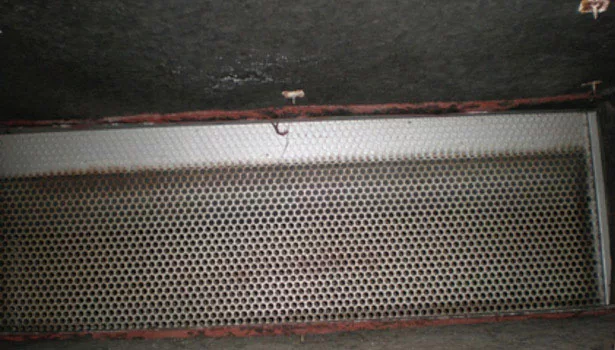
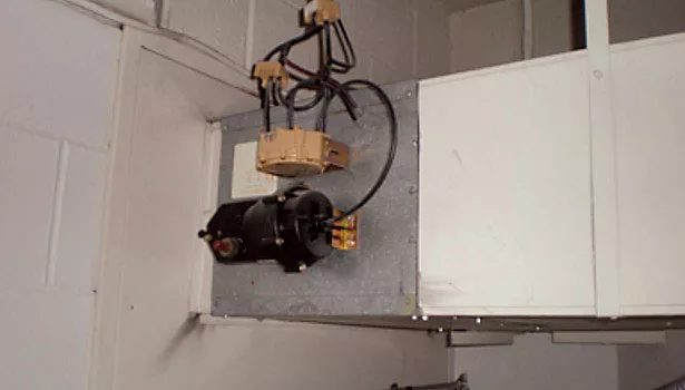
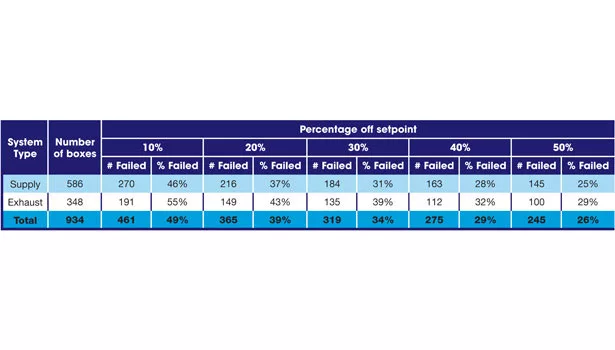
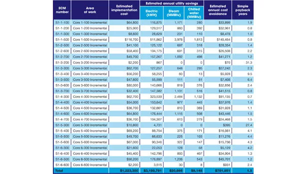
TABLE 2. Savings from fixing the air valves on each core and floor. To view this as a larger PDF, click here.
One of the worst-performing buildings I’ve had the pleasure to study was a 375,000-sq-ft laboratory building at a Midwest university.
The HVAC system consisted of twelve central station AHUs manifolded together to supply 26 risers that eventually went up several different building cores and fed reheat coils on the various floors. The exhaust systems were split out among 126 centrifugal exhaust fans located in penthouses centered above each of the building cores. The system was originally designed with constant volume reheat coils with constant volume fume hood and general exhaust.
Just a few years prior to our study, the university facility engineers pulled off a terrific job of phasing the demolition and reconstruction of the twelve 42,000-CFM air handlers in the basement. Each of these AHUs was equipped with a fan sized for 8.5 in of static pressure and powered by a 100-HP motor. Now that these units were fully operational, they were operating at almost full speed 24 hrs/day and consuming chilled water, steam, and electricity at an alarming rate.
During 2010, the facility operated at an average of 692 kbtu/sq-ft with an annual energy cost of roughly $3 million dollars. This building was the highest consumer of energy on campus. To understand how bad this is, the I2SL (formerly Labs 21) benchmarking tool lists a typical laboratory building in the Midwest at 355 kbtu/sq-ft. This means that this facility consumed almost two times the average for a building of its type.
Our scope of work was to study the building, make recommendations for improvement, estimate the installation cost of the recommendations, and predict the reduction in annual operating cost.
CURTAINS FOR THE AIR CURTAINS
The AHU and distribution scheme for the building was originally designed in 1969 as a constant volume reheat system. In 1990, they initiated a project that installed pneumatically controlled, retrofit VAV terminal units. Unfortunately, the consultant that completed the design drawings didn’t take into account the original designer’s intent for the supply air system. At each supply takeoff from the existing main air risers, a constant volume air curtain had been installed.
At one time, these air curtains were an advanced strategy to ensure proper air balance to the branch ductwork. The device was fairly simple. It consisted of a perforated plate, a fabric curtain, and a spring actuated roller. As the upstream pressure increased, the higher pressure unrolled the curtain to resist airflow. As the upstream pressure decreased, the lower pressure allowed the spring actuated curtain to roll up and allow more flow. The curtain simply rolled up and down to keep the airflow constant. Unfortunately, the curtains did not perform as intended due to their less than ideal field installation.
Once the VAV retrofit project was completed, with the air curtains still in place, very little energy was saved. Over the years since that project, spaces were renovated and upgraded with DDC variable volume terminal units, and as a result, some of the air curtains were removed. At the time of our study 20 years later, no one at the university could tell us definitively that they all had been removed. We eventually had a contractor go to every location that the original drawings showed an air curtain and physically verify if there was a curtain there or not. The results from that effort revealed that all 128 curtains were removed, except that the perforated plate still remained at 14 locations.
Figure 1 shows how the perforated plate looked after 35 years of service. Not surprisingly, several of the balancing dampers in the branch ductwork had to be throttled closed after the dirty perforated plate was removed.
I love history. Even if a facility has gone through numerous renovations, I always try to get my hands on the original HVAC drawings. Facility owners don’t always understand why I want the original drawings after the facility has been renovated, but they are usually accommodating. I like to review these to try and understand the original engineer’s intent. Sometimes, pieces of the original design never worked from day one. In other cases, the design worked perfectly for many years until it was modified to suit a renovation project.
FIXING VALVES AND HALVING THE CHANGES
This laboratory building has 998 air terminal units, each with half a dozen control points. That is a total of almost 6,000 control points for the air valves alone. There were also two generations of control systems that could not talk to each other and dozens of pneumatically controlled, failed, retrofit terminal units like the one in Figure 2.
One of my favorite things about fixing broken buildings is working with talented facilities staff. One of the controls programmers for the university pulled off a tremendous feat by giving us an excel spreadsheet of the valve position, airflow setpoint, measured airflow, space temperature, and space temperature setpoint for 934 of the air valves. After analyzing this data, we found that over 25% of the air valves deviated from their airflow setpoint by more than 50% and less than half of them were within 10% of their airflow setpoint. Table 1 shows results from our report.
We concluded from this data that roughly half of the air valves were not working properly and needed attention. This data gave us the evidence to confidently recommend an air valve recommissioning project.
The university started fixing some of the terminal units but quickly found that this was going to be a huge task. They found very few boxes that were completely functional. They found everything from failed actuators, to actuators slipping on damper shafts, to broken dampers, to dirty airflow stations that gave erroneous readings. To make the task even more challenging, access to the air valves was difficult due to how they are installed and how difficult it is to schedule access to the laboratory. When there are thousands of dollars of research going on in a laboratory, you can’t just walk in with your tool box and start tearing things apart. They had to schedule their time two weeks in advance, which made completing their work even more difficult.
Keeping up on repair and maintenance for these air valves was a huge task, and because the facilities engineers are spread so thin, it just didn’t get the attention it needed. One university employee likened this building to a bleeding patient. In order to save it, the uncontrolled air (bleeding) had to stop.
A large amount of this bleeding airflow was relieved directly out of the atrium through relief louvers mounted adjacent to the skylights. The building is so positively pressurized that roughly 30,000 CFM of conditioned air was being relieved to the outside 24 hrs/day.
What has also happened to this facility is that when an area is renovated, the money comes from a grant that a researcher has obtained through various funding sources. Naturally, the researcher does not want to spend money renovating spaces outside of their own areas, so spaces such as common corridors, atriums, bathrooms, and back-of-house spaces don’t get upgraded. This has left the university with a mix of modulating air valves, failed pneumatic retrofit dampers, and in some cases failed retrofitted dampers upstream of newly installed modulating air valves. The old retrofit dampers were typically failed fully open just because they were manually opened by the balancer in response to a complaint for more cooling. Since these zones still had functioning reheat coils, increasing the airflow was an easy fix for these complaints. Unfortunately, this taxed the air system further.
The original design provided for roughly 13 ach of supply and exhaust in each laboratory. The university’s standard was now only six air changes. This meant that significant energy could be saved by lowering the minimum flow rates on the air valves. The challenge to make that happen was fixing the broken air valves, installing new air valves, and replacing the retrofit air valves with new ones all while scheduling very small windows of access to the spaces.
The calculation of the energy savings was fun. We used compressible fluid flow analysis software to model the supply ductwork. We modeled the take-off on each supply branch on every floor and every riser all the way back down to the 12 AHUs in the basement. We prepared an excel spreadsheet with the desired air valve flow rates and uploaded the supply air flow values into the model. From this, we could tell what the required static pressure at the AHUs needed to be and the air valve that was the most hydraulically remote.
I like energy calculations. Sometimes I use them to justify creating a cool new spreadsheet (yes, I am a nerd). On this project, I created a master laboratory energy calculation spreadsheet. We typically use spreadsheets instead of energy modeling software to calculate energy for laboratories. I have found that energy modeling software is great for buildings where the envelope load plays a major factor in the energy consumption. For most laboratory buildings, the energy consumption is primarily driven by the exhaust and minimum ventilation rates, so the envelope load is a minor factor. Using the spreadsheet bin analysis, we determined the annual energy consumption based on its current condition and how much energy could be saved by replacing air valves, fixing air valves, adding new air valves, and reducing minimum air change rates to six air changes per hour. Table 2 shows our results.
TWENTY-SEVEN PERCENT
Knowing that it might be difficult to fund and schedule the entire project at once, we broke down the savings and incremental cost on a core by core basis. This allowed the university to know which areas needed the most work, opening the option to fund multiple smaller projects instead of one large project.
Our study calculated a total energy savings of $1.3 million a year, with $800,000 of that being contributed to the air valve failures.
It is no surprise that one of the biggest contributors to a building’s energy consumption is conditioning of outside air. By fixing the broken air valves, installing air valves at locations where the air is not controlled, and reducing the minimum air change rate from 13 to six per hour, this building would be able to save $800,000 dollars annually. That equates to a 27% reduction in annual energy cost.
Looking for a reprint of this article?
From high-res PDFs to custom plaques, order your copy today!


